
Remember me
Digital holographic microscopy (DHM) [1–3] is a powerful optical imaging technique based on wavefront recording and reconstruction. The DHM records digital holograms by capturing the interference fringes between an object beam and a reference beam on an image sensor. The recorded holograms are subsequently processed using computational algorithms to reconstruct the object wavefront with high efficiency and enable precise quantitative analysis. DHM is particularly well-suited for observing micro- to nanoscale structures [4–6], offering advantages such as high spatial resolution and high phase sensitivity. It enables label-free, non-destructive, and minimally invasive full-field amplitude and phase imaging, making it widely applicable in fields such as biomedical imaging, materials science, and microscale metrology.
Conventional DHM systems are based on interferometric architectures such as the Michelson [7, 8] or Mach–Zehnder interferometers [9, 10]. In these interferometers, the object and reference beams travel through separate optical paths, rendering them sensitive to mechanical vibrations and environmental disturbances. These perturbations may reduce interference fringe contrast and increase phase noise, thereby degrading image quality. To improve system stability, CP configurations have been developed [11–13]. These configurations allow the object and reference beams to share most of the optical path, effectively minimizing the influence of external disturbances and enhancing the stability and accuracy of phase imaging.
Among various CP DHM configurations, two prevalent designs are lateral shearing [14–16] and point diffraction interferometry [17–19]. Lateral shearing interferometry (LSI) does not rely on wavelength-sensitive diffraction optical elements, featuring a simple optical architecture compatible with broadband or white-light illumination while also supporting multifocal imaging. However, LSI exhibits limitations when handling dense or complex samples, as its shearing nature often leads to overlap with adjacent structures and restricts the field of view (FOV). Therefore, applying LSI requires consideration of factors such as sample sparsity and structural overlap. In contrast, point diffraction interferometry utilizes physical grating to split the beam and employ pinhole filtering to generate a reference beam. When combined with off-axis interference and a 4–f imaging system, this approach enables full-field wavefront reconstruction without the need for sample sparsity and offers greater flexibility for implementing multi-beam interference. CP DHM based on point diffraction (CP-DHM) has been successfully applied in dynamic cell monitoring [20–22] and semiconductor surface metrology [23–25], demonstrating high practicality and accuracy.
To meet the diverse requirements of multi-wavelength and multi-scale imaging in various application scenarios, the development of CP-DHM systems with multi-wavelength operations and varifocal capabilities has become an important research objective. Multi-wavelength operation enables the observation of an object within the same FOV under different wavelengths, revealing variations in its physical properties, such as transmittance, reflectance, and refractive index, thereby providing a deeper understanding of the object [26–28]. Varifocal allows flexible magnification adjustments, facilitating comprehensive observation from macroscopic distribution to microscopic detail [29–31]. However, integrating these functions into point diffraction-based CP-DHM systems poses several challenges. First, due to the grating equation, the diffraction angle of the physical grating varies with the wavelength of the incident laser, necessitating precise repositioning of the pinhole to maintain effective low-pass filtering when switching wavelengths. Although this can be dynamically controlled using a spatial light modulator (SLM) [32, 33], the pixel resolution of the SLM may limit filtering precision. Second, varifocal adjustments introduce varying degrees of optical aberrations [34], which can cause defocusing at the pinhole filtering plane. This degrades the quality and power density of the reference beam, reduces fringe contrast, and impairs reconstruction clarity. Finally, modules with switchable varifocal capabilities may cause misalignment between the optical and mechanical axes, resulting in additional aberrations that increase system calibration complexity and potentially affect imaging accuracy.
In response to these challenges, this study proposes a novel design method for the multi-wavelength varifocal CP DHM (MWV-CP-DHM). The proposed system overcomes the limitations of conventional architectures in wavelength adaptability and varifocal flexibility by integrating CP design, multi-wavelength operations, and varifocal capabilities. Leveraging computational holography and dynamic control via the SLM, the system effectively mitigates technical bottlenecks such as diffraction angle errors, chromatic dispersion, and aberration drift. Unlike conventional systems with fixed illumination and magnification that lack adaptability, the developed MWV-CP-DHM can stably record and reconstruct holograms under varying wavelength and varifocal conditions, significantly enhancing application flexibility and operational robustness. Experimental results confirm that the proposed method operates reliably under multi-wavelength and varifocal conditions, delivering high-contrast, high-quality reconstructed images. These findings underscore the system’s potential and scalability in precision optical metrology, biomedical imaging, and multi-scale observation.
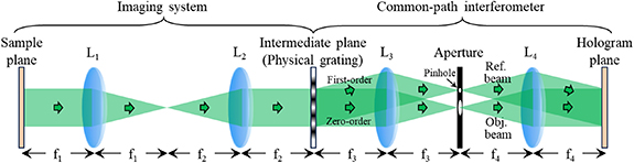
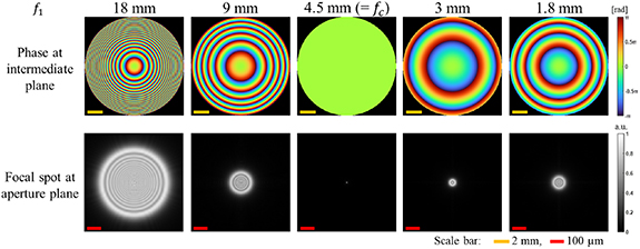
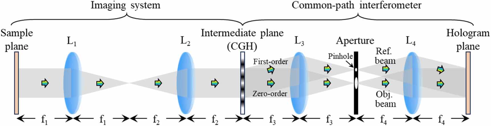
2.1. Concept of conventional CP-DHMThe conceptual diagram of the conventional CP-DHM based on the point diffraction method is shown in figure 1. The CP-DHM mainly comprises two parts: a front-end imaging system and a back-end holographic interference module. Initially, the object is imaged onto the intermediate plane, which is the back focal plane of the second lens (L2), through a 4–f imaging system. At this intermediate plane, a physical grating is placed as the key component of the holographic interference module. This physical grating diffracts the light emitted from the object into two parts: the zero-order diffraction (object beam) that propagates along the optical axis and the first-order diffraction (reference beam) that is deflected at an angle  . Subsequently, a pinhole is placed at the back focal plane of the third lens (L3) at the location corresponding to the reference beam. Due to its low-pass filtering effect, the pinhole effectively removes high-frequency object information contained in the reference beam, yielding a clean and smooth wavefront to serve as the reference wave. Finally, the object beam and the reference beam converge and interfere at the hologram plane where the sensor is located, forming a digital hologram that contains complete object information. However, the conventional CP-DHM architecture still faces certain challenges and limitations in multi-wavelength operations and varifocal capabilities, which require further optimization and development.
Figure 1. Conceptual diagram of the conventional CP-DHM. L: lens, Obj. beam: object beam, Ref. beam: reference beam.
Download figure:
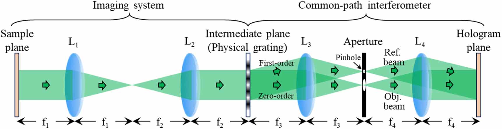
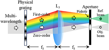
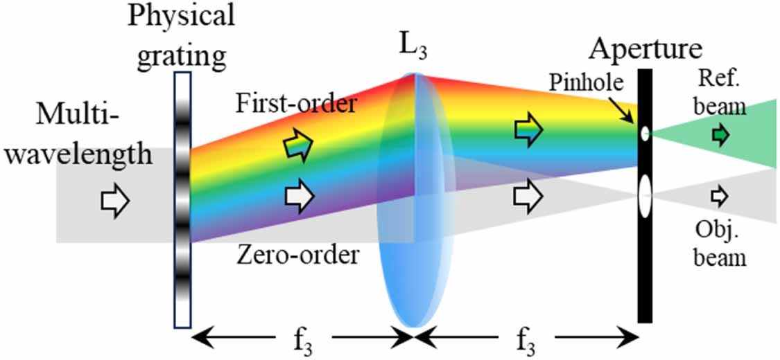
Standard image High-resolution image 2.2. Problems of multi-wavelength in conventional CP-DHMWhen employing the multi-wavelength light source in the conventional CP-DHM, the spatial frequency of the physical grating remains fixed, causing the diffraction angle to vary with the wavelength of the incident beam. The schematic diagram is shown in figure 2. An increase in wavelength results in a larger diffraction angle, while a decrease leads to a smaller diffraction angle. These angular variations directly affect the position of the reference beam at the back focal plane of lens L3. Consequently, maintaining a fixed pinhole position may disrupt the intended low-pass filtering of the reference beam, potentially resulting in partial or complete attenuation of the reference beam. Such degradation can diminish interference contrast or, in severe cases, eliminate interference entirely.
Figure 2. Schematic diagram of a physical grating with fixed spatial frequency under multi-wavelength illumination. As the wavelength increases, the diffraction angle of the first-order beam increases.
Download figure:
Standard image High-resolution image 2.3. Problems of varifocal in conventional CP-DHMTo accommodate the demands of multi-scale imaging, microscopy systems commonly incorporate varifocal capabilities to flexibly adjust magnification. A primary approach for achieving such capabilities is to switch objectives with different magnification levels. Since the magnification of an objective is directly proportional to its numerical aperture (NA) and inversely proportional to its focal length, changing the objective effectively implements a varifocal operation.
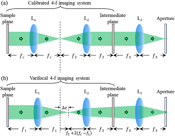
Figure 3 shows the schematic diagram of a CP-DHM equipped with varifocal capability. To isolate and analyze the optical effects introduced solely by the varifocal operation, there is no physical grating placed at the intermediate plane in this concept diagram. Figure 3(a) shows a calibrated 4–f imaging system, where the object is positioned at the front focal plane of the Lc, and the image is formed at the back focal plane of L2, which serves as the intermediate plane. When the objective is replaced by another L1 with a different focal length, as shown in figure 3(b), the system ideally should maintain the relative alignment between the object plane and the intermediate plane. However, due to the change in focal length, the distance between the object and L1 must be readjusted. This adjustment causes the back focal point of L1 to deviate from the front focal plane of L2, introducing a focal mismatch quantified by  . This mismatch introduces spherical aberration at the intermediate plane. The spherical aberration can be expressed as
 ![$}\left[ + } \right)} \right]$](https://content.cld.iop.org/journals/2040-8986/28/2/025703/revision2/joptae3fabieqn3.gif) , where
, where  is
is  ,
,  ,
,  is working wavelength, and
  and
and  are spatial coordinates. As a result, the focal spot at the back focal plane of L3 becomes enlarged, which may reduce the filtering efficiency and optical power density of the first-order reference beam. This leads to a decrease in interference fringe contrast in the hologram and ultimately degrades the quality of the reconstructed image.
Figure 3. Schematic diagram of the varifocal configuration in CP-DHM. (a) A calibrated 4–f imaging system using Lc. (b) A varifocal configuration in which Lc is replaced with L1.
Download figure:
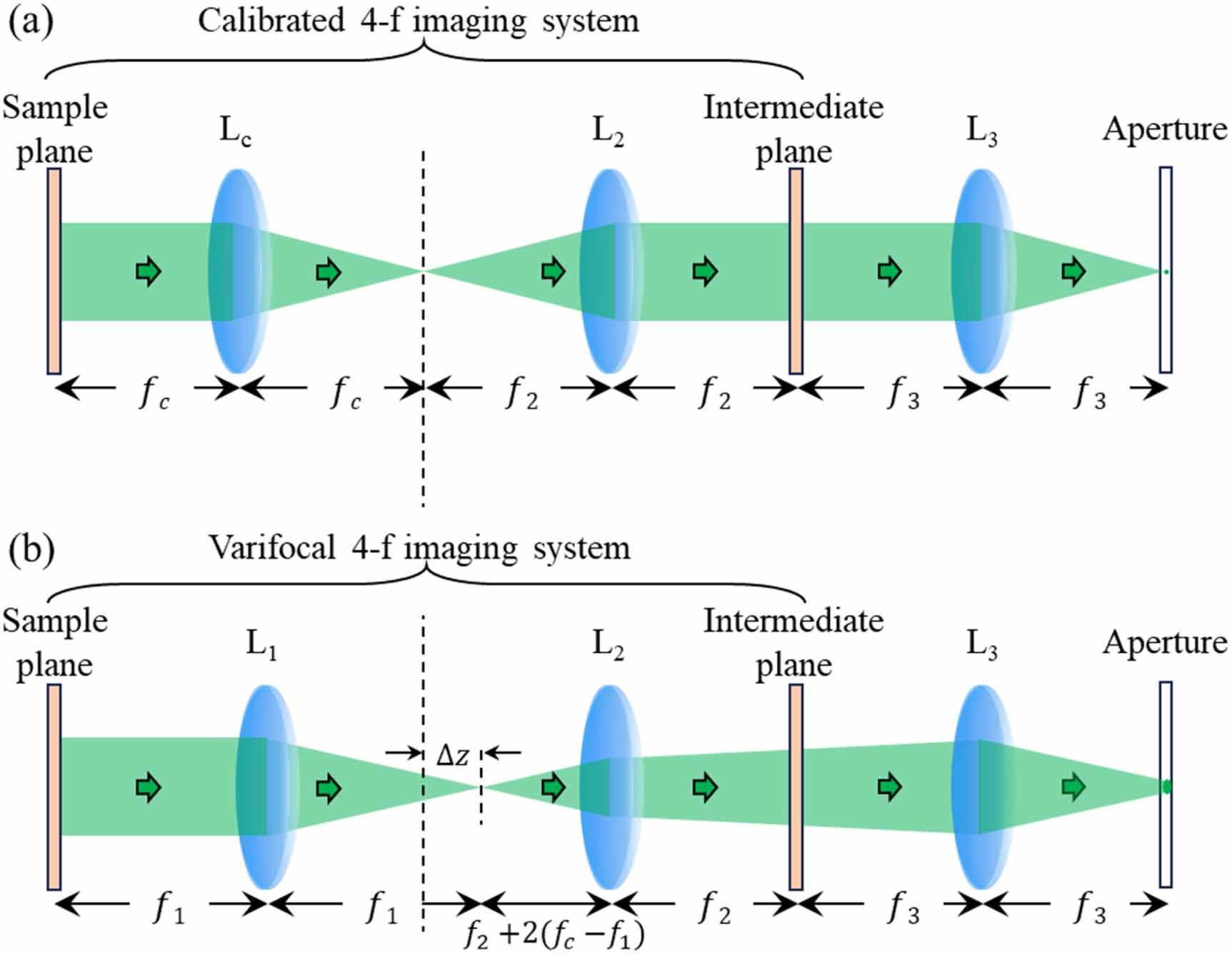
Standard image High-resolution imageFigure 4 presents the corresponding simulation results. The  refers based on the focal length specifications of objectives, with
  = 4.5 mm (corresponding to a 40× objective) used as the baseline for system calibration. To investigate the effects of varifocal,
  is subsequently replaced with the longer focal length (18 mm, 9 mm) and the shorter focal length (3 mm, 1.8 mm). The simulation results reveal that when
  is increased, the phase distribution exhibits negative spherical curvature, whereas a decrease in
  results in positive spherical curvature. Furthermore, the focal spot size becomes significantly larger in both scenarios, indicating that inadequate optical alignment or calibration during varifocal operation leads to an increase in the focal spot size of the CP-DHM system. This degradation adversely affects the filtering performance and reduces the quality of holographic interference reconstruction.
Figure 4. Simulation results of the phase distribution at the intermediate plane and the focal spot at the aperture plane in the varifocal system. Rad: radian, a.u.: arbitrary unit.
Download figure:
Standard image High-resolution image 2.4. Proposed method of MWV-CP-DHMConsidering the challenges associated with multi-wavelength operations and varifocal requirements in CP-DHM systems, this study presents a novel design approach for a MWV-CP-DHM. This approach addresses the limitations of conventional CP-DHM in terms of wavelength adaptability and varifocal flexibility, establishing a highly stable and broadly compatible holographic imaging platform. As shown in figure 5, the MWV-CP-DHM system builds upon the foundational structure of conventional CP-DHM while introducing two key innovations. First, the physical diffraction grating conventionally used for reference beam filtering is replaced with a phase-only SLM. Second, by leveraging the programmable nature of the SLM, the system dynamically generates computer-generated holograms (CGHs) tailored to specific wavelength and focal length conditions. To support these functions, four lenses (L1–L4, with focal lengths f1–f4) are integrated into the system. L1 and L2 form a 4–f imaging relay with a magnification of f2/f1, ensuring that the beam size at the SLM exceeds the panel aperture to maximize CGH utilization and diffraction efficiency. L3 and L4 constitute the CP interferometer in which the separation between the zero- and first-order diffraction components at the aperture plane follow D0−1 = f3 × tanθ, where θ denotes the tilt angle of the reference beam, allowing f3 to be selected to provide sufficient spacing for pinhole filtering. The final system magnification is given by (f2/f1)×(f4/f3). The CGHs designed in this work are engineered with customized phase distributions to meet the spatial frequency requirements of different wavelengths and to correct for spherical aberrations caused by focal length variations. The designed CGH can be expressed as ![$C + }\left[ } + y \cdot }} \right)} \right] \times }\left[ }}} \times \left( + } \right)} \right]$](https://content.cld.iop.org/journals/2040-8986/28/2/025703/revision2/joptae3fabieqn15.gif) , where the constant term C corresponds to the object beam, commonly referred to as the zero-order term. The exponential terms represent the reference beam and consist of two components: the blazed grating term,
, where the constant term C corresponds to the object beam, commonly referred to as the zero-order term. The exponential terms represent the reference beam and consist of two components: the blazed grating term, ![$}\left[ } + y \cdot }} \right)} \right]$](https://content.cld.iop.org/journals/2040-8986/28/2/025703/revision2/joptae3fabieqn16.gif) , where
, where  and
and  denote tilt angle; and the spherical wave term,
 ![$}\left[ }}} \times \left( + } \right)} \right]$](https://content.cld.iop.org/journals/2040-8986/28/2/025703/revision2/joptae3fabieqn19.gif) , where
, where  is the focal length of the virtual lens, imparting a quadratic phase profile that corrects for aberration wavefront. The custom design CGH ensures high-quality interference between the object and reference beams across varying imaging conditions. Through the CGH modulation strategy, the MWV-CP-DHM system enables high-fidelity holographic recording and reconstruction under both multi-wavelength and varifocal configurations. The design enhances the system’s adaptability to wavelength changes while maintaining consistent interferometric fringe contrast and phase sensitivity across different imaging conditions.
Figure 5. Conceptual diagram of the MWV-CP-DHM. The use of customized CGH design facilitates multi-wavelength and varifocal holographic recording and reconstruction in the CP-DHM system.
Download figure:
Standard image High-resolution imageTo assess the feasibility and imaging stability of the proposed MWV-CP-DHM, we performed a series of experiments employing three representative wavelengths and three objectives with distinct magnifications. By systematically varying both wavelength and magnification, we characterized the system’s imaging performance and demonstrated its robustness, operational versatility, and high-quality reconstruction capabilities under diverse imaging conditions.
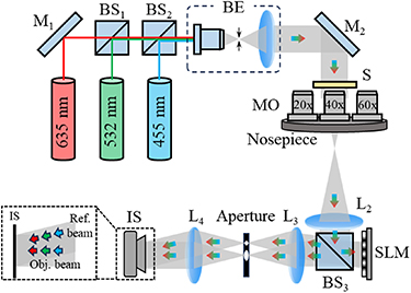
The experimental setup of the MWV-CP-DHM is shown in figure 6. The light source consists of three representative visible-wavelength lasers at 455 nm (blue), 532 nm (green), and 635 nm (red). The wavelength can be selected individually according to the experimental requirements. Each laser beam is first expanded by a beam expander before illuminating the sample, where the object wavefront is captured by the microscopic imaging system. The microscopic imaging system employs three objectives with different magnifications and NAs, namely 20×/NA 0.40, 40×/NA 0.65, and 60×/NA 0.85, mounted on a rotating nosepiece to achieve multi-scale imaging. The object wavefront then passes through the  with a focal length of 175 mm to complete the imaging of the object to the intermediate plane. To achieve optimal interference under different wavelength and magnification conditions, the phase-only SLM (pixel number: 1080 × 1080, pixel size: 6.4 μm) is positioned at the back focal plane of
  . The SLM displays CGHs tailored to each wavelength and magnification setting, modulating the object beam into zero-order and first-order diffraction components. The CGH designs incorporate wavelength-specific gratings, spherical aberration correction, and phase modulation profiles appropriate for each wavelength, ensuring consistent interference quality across all imaging conditions. In the CP interferometric module, the lenses
  (focal length: 100 mm) and
  (focal length: 150 mm) form a 4–f system to relay and magnify the interference signal generated by the object beam. At the back focal plane of
  , a 20 µm pinhole is positioned at the focal point of the first-order diffracted beam to filter out high-frequency object information, thereby converting it into a uniform, planar reference beam. Finally, the object beam and the reference beam interfere at the hologram plane, where the hologram is captured by a monochrome image sensor (pixel number: 2500 × 2500, pixel size: 2.74 µm), completing the holographic recording process. The FOVs under 20×, 40×, and 60× objectives are 204 × 204 µm2, 102 × 102 µm2, and 68 × 68 µm2, respectively. In the system setup, the apochromatic lenses are employed to minimize chromatic aberration induced using multiple wavelengths. The angular spectrum method is employed for hologram reconstruction.
Figure 6. Experimental setup of the MWV-CP-DHM. Although beams of different wavelengths share a common optical path, the sample is illuminated with a monochromatic beam at any given time. M: mirror, BS: beam splitter, BE: beam expander, S: sample, MO: objective, L: lens, SLM: spatial light modulator, IS: image sensor.
Download figure:
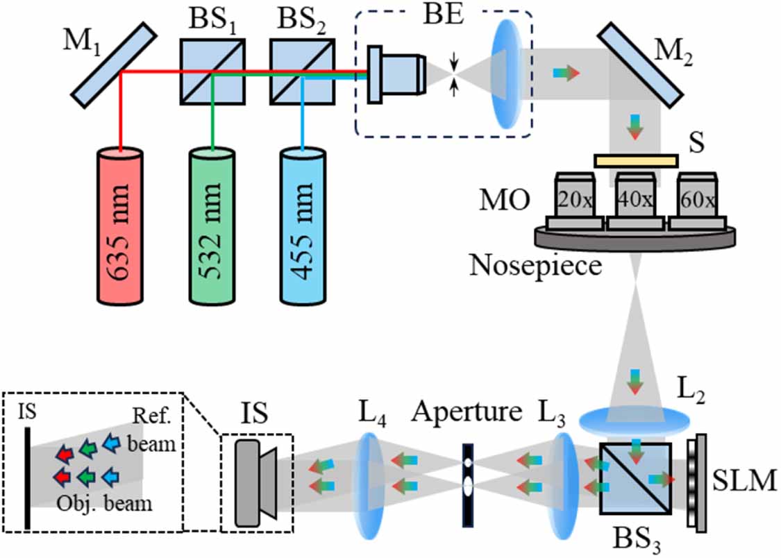
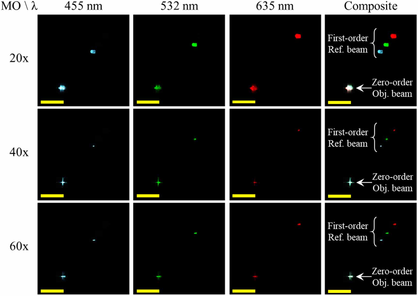
Standard image High-resolution imageDuring the system setup of the MWV-CP-DHM, the system calibration is performed using the 532 nm laser in combination with a 40× objective lens. Under these conditions, the design tilt angle of the CGH is set to  . As shown in figure 7, when the CGH designed for the calibration configuration is applied to other wavelengths and magnifications, the first-order position observed at the focal plane shifts further from the zero-order position as the wavelength increases. Additionally, with the 20× and 60× objectives, due to spherical aberrations introduced by changes in focal length, the focal spot sizes of both the zero-order and first-order beams are larger than those produced by the 40× objective.
Figure 7. Focal spot distributions at the back focal plane of L3 using calibrated CGH for each wavelength and objective magnification. The distance between the first-order and the zero-order term increases with increasing wavelength. The original images are in grayscale, and the color representation is achieved through digital staining processing for better visualization. Scale bar: 1 mm.
Download figure:
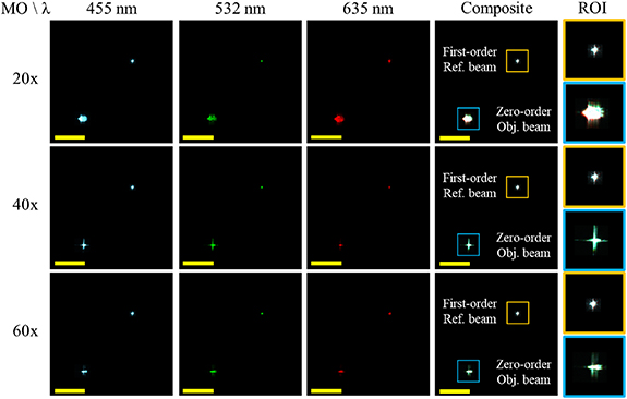
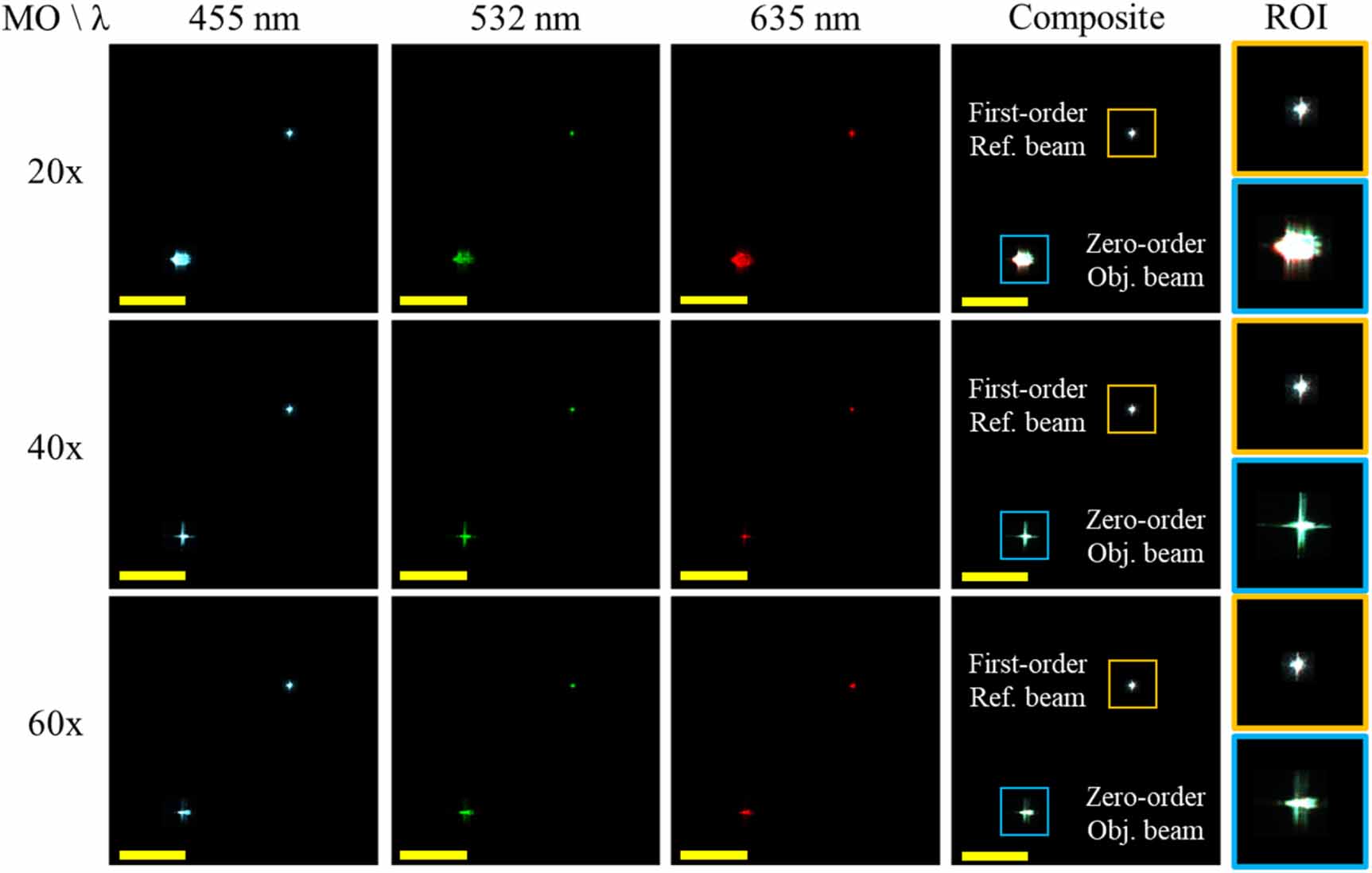
Standard image High-resolution imageThe CGH parameters designed for each wavelength and objective magnification are summarized in table 1. During the experimental setup process, the image sensor is first positioned at the back focal plane of L3, and the customized CGHs are projected to verify the focal spot positions of the zero-order and first-order terms. Subsequently, the design parameters of the CGH (tilt angles  and
and  , and the focal length of the virtual lens
  ) are finely adjusted to ensure that the first-order focal spot position remained in focus and in the same position under various imaging conditions. The corresponding focal spot distributions at the back focal plane of L3 are presented in figure 8. The experimental results clearly demonstrate that the first-order reference beams consistently converge to the same spatial location, regardless of variations in wavelength or magnification. This high degree of spatial stability is primarily attributed to the correction of spherical aberrations introduced by the objective lens, which is implemented at the intermediate plane during CGH design. Such correction significantly reduces beam divergence and sharpens the first-order focal spot after propagation. As a result, precise placement of a pinhole at this calibrated focal position facilitates robust and repeatable hologram recording under both multi- wavelength and varifocal conditions. This alignment strategy ensures optical path consistency and enhances the fidelity of the reconstructed holographic information.
Figure 8. Focal spot distributions at the back focal plane of L3 using CGHs tailored for each wavelength and objective magnification. The blue and orange boxes denote the zoom-in regions corresponding to the zero-order object beam and the first-order reference beam, respectively. The first-order reference beams are spatially co-localized, demonstrating effective multi-wavelength and multi magnification alignment and focus consistency. The original images are in grayscale, and the color representation is achieved through digital staining processing for better visualization. ROI: region of interest. Scale bar: 1 mm.
Download figure:
Standard image High-resolution imageTable 1. Parameters used for CGH design. Inf denotes an infinite focal length.
MO455 nm532 nm635 nm


 20×1.2361.524−71.2091.487−71.1971.481−740×1.2271.535Inf1.2001.500Inf1.1921.489Inf60×1.2241.5341001.1951.5001001.1861.487100
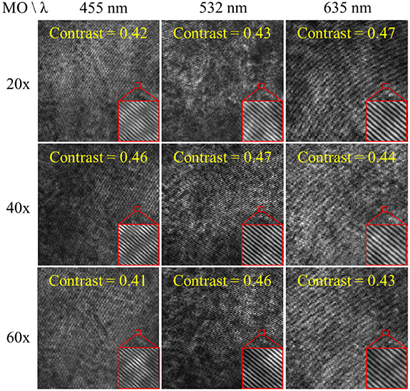
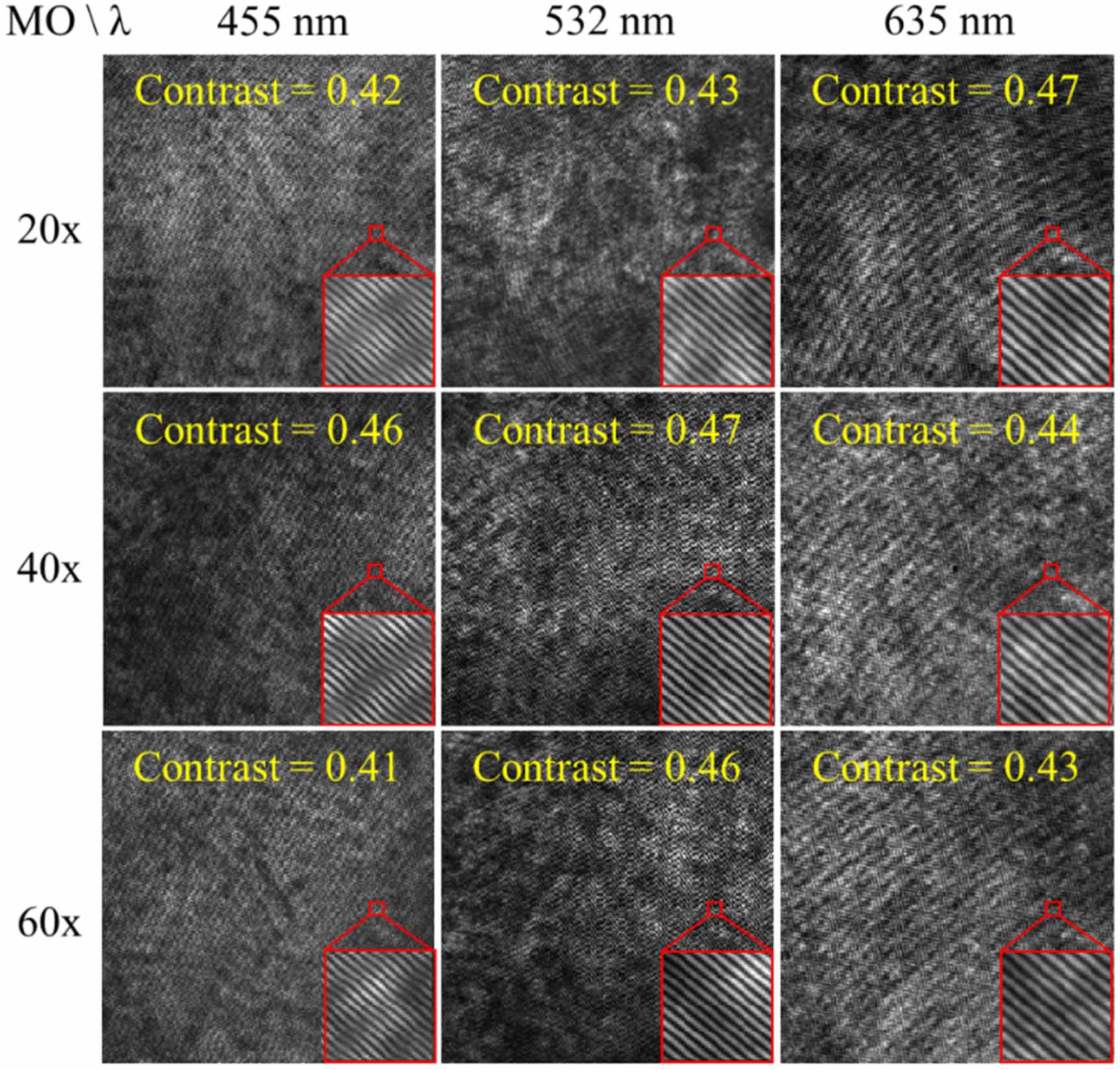
The background holograms recorded in the absence of an object are shown in figure 9. The interference fringe contrast is evaluated using the formula  , where
  and
and  denote the maximum and minimum intensities of the interference fringes, respectively. Experimental results indicate that the average interference fringe contrast of the nine background holograms under different conditions exceeds 0.4, which is sufficient to support reliable wavefront recording and subsequent phase reconstruction.
Figure 9. Background holograms recorded at different wavelengths and objective magnifications.
Download figure:
Standard image High-resolution imageTo further correct system aberrations and reduce background noise, an additional reference background hologram was recorded without sample. Phase compensation was then performed by subtracting the background phase, resulting in high-quality, aberration-free phase reconstruction. Since the aberration correction at the intermediate plane is applied exclusively to the first-order reference beam, the zero-order object beam remains affected by the aberrations introduced by the varifocal mechanism associated with the use of objectives of different magnifications. Both the original and aberration-compensated phase maps for various wavelengths and magnifications are shown in figure 10. In the original phase maps, noticeable spherical aberrations are observed at 20× and 60× magnifications, with curvature trends consistent with simulation results—negative curvature for 20× and positive curvature for 60×. The compensated phase distributions demonstrate strong consistency and effective aberration removal. To further quantify the compensation performance, the standard deviation (STD) of phase distribution was used as a metr
Comments (0)