
Remember me
Electroporation induced by pulsed electric fields (PEFs) has attracted increasing interest in the biomedical field due to their non-thermal effects, minimal invasiveness, and ability to promote tissue regeneration [1, 2]. Several PEF-based therapies have successfully progressed from laboratory research to clinical applications. Among them, the NanoKnife, as a prominent device, has been widely adopted for tumour ablation in organs such as the prostate and melanoma tumors [3, 4]. It employs microsecond-range pulsed electric fields to enhance membrane permeability and elicit localized immune responses. More recently, nanosecond pulsed electric fields (nsPEFs) have emerged as a highly more promising therapeutic strategy, offering enhanced intracellular penetration, the ability to interact with organelles, and the potential to induce immunogenic cell death [5]. Despite their potential, nsPEF-based treatments remain at the experimental stage. To make these treatments usable in clinics, a system is needed that can deliver carefully controlled electrical pulses. This system depends on two main parts: high-voltage pulse generators and specially designed electrodes [6, 7].
Typically, electrodes can be classified into two main types based on the morphology of biological samples: needle-type electrodes, used for solid tissues such as tumours [8], and container-type electrodes, used for cell suspensions [9]. In this study, we focus on container-type electrodes specifically designed for in vitro nsPEF-based electroporation. To select an appropriate container-type electrode, several critical factors should be taken into serious consideration, including the pulse parameters, the bio-impedance, the desired electric field distribution, and the Joule dissipation.
Under high-voltage nsPEF-based exposure, the various cuvettes utilized in in vitro experiments should support cell suspensions—which typically exhibit high conductivity (low impedance)—while maintaining uniformity of the electric field. However, this structure tends to result in low electrical impedance, which can lead to excessive current flow during high-voltage pulsing [6]. To address this issue, planar circular interdigitated electrodes with a 1-mm gap have been introduced, which suports high-conductivity biological samples and allows real-time microscopic visualization of living cells during electroporation [10]. However, it is diffcult to achieve a perfectly uniform electric field distribution. A modified version is developed to further enhance compatibility with real-time microscopic analysis [11]. Beyond static setups, a scalable continuous-flow platform is proposed to enable efficient and reproducible electroporation of small-volume cell suspensions. This system is suitable for cellular therapies due to its scalability. However, its releatively low operating voltage limits its applicability in certain high-voltage stimulation experiments [12]. In addition, capillary and wire-type electrodes are designed for high-resistivity samples, while minimizing cell loss and enhancing throughput in high-volume experiments. Despite these advantages, their structural design compromise the uniformity of the electric field across larger sample areas [13]. Overall, although these designs offer tailored solutions for specific experimental needs, each approach inevitably presents notable limitations that constrain their broader applicability and experimental performance.
In this work, a commercial cuvette is initially employed as a container-type electrode for a 2 kV pulse generator. However, it faces challenges in handling tens of amperes of current or more. To simultaneously achieve uniform electric field distribution and support high-current operation in high-voltage pulse systems, a novel grid-patterned cuvette is proposed. To verify the working performance, the proposed grid-patterned cuvette was fabricated and measured. The experiment results show its effectiveness in overcoming the limitations of commerical cuvettes.
The remainder of this paper is structured as follows. Section 2 describes the design and development of the grid-electrode cuvette. Section 3 presents the fabrication process and experimental evaluation of the proposed cuvette. Finally, section 4 summarizes the findings and suggests potential directions for future research.
2.1. Material and administration of nsPEFIn this work, saline is considered as a biological sample with a conductivity of 1.2 S m−1 and a relative permittivity of 60. Cuvettes with 1 mm gaps are employed in vitro nsPEF-based cell stimulations. A custom-designed pulse generator delivers 2 kV, 50 ns pulses to saline samples with varying volumes, operated under the maximum current threshold of 100 A. Considering the fundamental frequency of the applied pulse is approximately 20 MHz, the bioelectric properties of saline samples are evaluated to ensure accurate characterization under this high-frequency condition. To ensure the safety of physical operation, a 40 μl volume of saline is loaded into various cuvettes, and its electrical response is characterized through current–voltage (I-V) measurements.
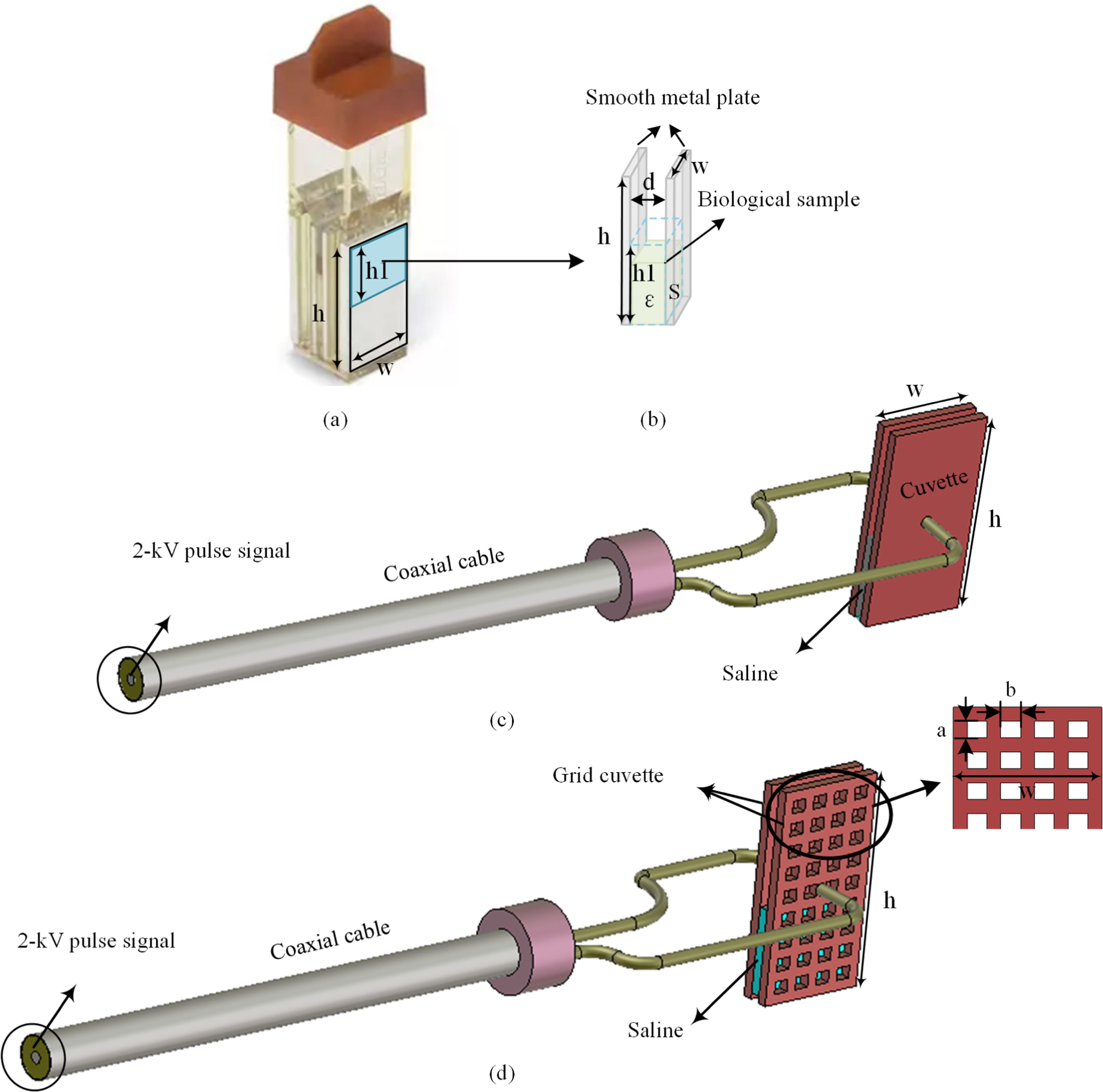
2.2. Evolution of gird cuvetteAs illustrated in figure 1(a), a typical commercial cuvette consists of a pair of parallel electrodes with a dimension of 10.7 mm × 20.97 mm, enclosed by a transparent sealing structure. However, the actual available capacity corresponds only to the blue-highlighted region measuring 10.7 mm × 10 mm, which can be modelled as a parallel-plate capacitor as shown in figure 1(b). The bioelectric resistance—commonly referred to as impedance—of the biological samples can be defined as follows:

where d is the gap between electrodes, S is the cross-section area between electrode and sample, ρ and σ represent the electrical resistivity and electrical conductivity, respectively.
Figure 1. (a) Commercial cuvette with dimensions: h = 20.97 mm, w = 10.7 mm, h1 = 10 mm, d = 1 mm, (b) simplified equivalent model of the commercial cuvette. The light-shaded area represents the biological sample. The dashed outline indicates the maximum available fill capacity. (c) case 1: EM model of the commerical cuvette and transmission line, and (d) case 2: EM model of the proposed grid cuvette and transmission line.
Download figure:
Standard image High-resolution imageAs indicated by equation (1), the resistance of a biological sample is strongly influenced by its geometric configuration. Specifically, as electrode gap d is fixed, the impedance can only be increased by reducing the effective cross-sectional area available for current conduction. This constraint motivates the design of a grid-patterned cuvette, which increases impedance by limiting the current conduction area.
To evaluate the performance of the proposed grid-patterned cuvette, it is modeled and simulated using CST Studio Suite 2023. The design consists of a pair of grid electrodes separated by a 1-mm gap, with each electrode measuring 10.7 mm × 20.97 mm in size but avalibale capacity with 10.7 mm × 10 mm. The electromagnetic (EM) field distributions of the biological samples are simulated in the Electrostatic Domain under the potential difference of 2 kV. Furthermore, the resulting impedances are analyzed in the Time Domain under 2 kV excitation across a frequency from 0 to 1 GHz. To accurately approximate realistic in vitro experimental conditions, two models, designated as Case 1 and Case 2, are simulated and compared. Both models maintain the same fixed gap of 1 mm and electrode dimensions of 10.7 mm × 20.97 mm. Each configuration with an avaliable capacity of approcimately 100 μl incorporates identical coaxial excitation and contains a 40 μl saline sample, enabling a comprehensive evaluation of electrical properties under practical loading conditions, as illustrated in figures 2(c) and (d).
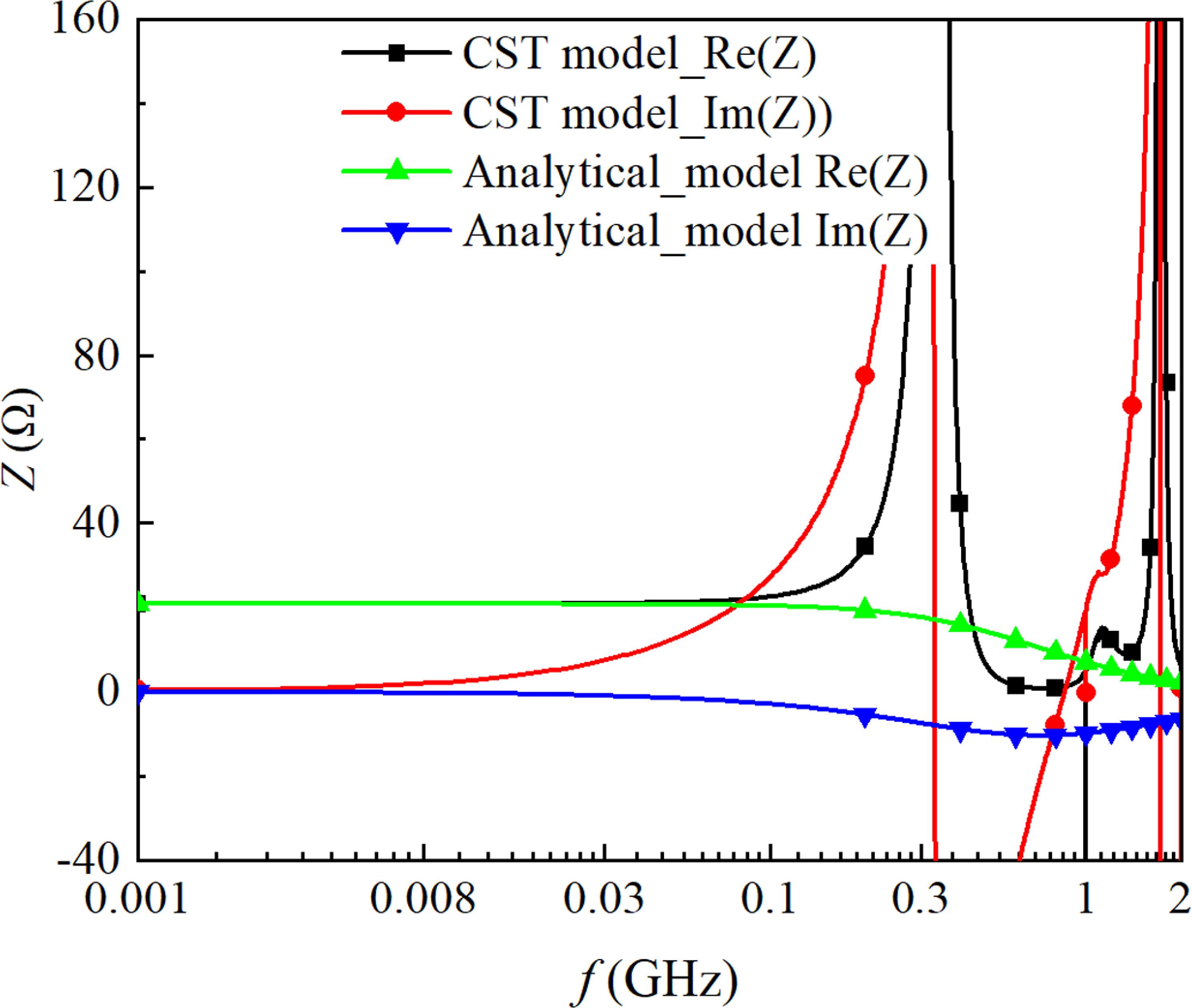
Figure 2. Impedance of 40 ul saline versus frequency in the standard cuvette. The black and red lines are the real and imaginary parts of the CST model. The green and blue lines are real and imaginary parts of the analytical model.
Download figure:
Standard image High-resolution image 2.3. Impedance enhancement of the proposed grid-patterned cuvetteUnlike a purely resistive load, the cuvette filled with saline exhibits complex impedance characteristics due to the frequency-dependent conductivity of the saline when exposed to the given nsPEFs. The equivalent electrical impedance, denoted as Ze, is defined by the analytical equation provided in [14],

where  , f and ε respresent the frequency and the absolute permitivity respectively. Within the desired frequency bandwidth, permittivity variation with frequency is negligible.
Initially, a commercial cuvette is used as a reference benchmark. Figure 2 presents the impedance characteristics of a 40 μl saline based on Case 1 model. Full-wave EM simulations reveal three distinct impedance behaviors. At low frequencies (below 5 MHz), the impedance is resistive, dominated by the ionic conductivity of the saline. In the intermediate frequency (from 5 MHz to 200 MHz), the dielectric component of the saline becomes more complex, leading to a noticeable rise in the reactance. At higher frequencies, a pronounced resonance is observed around 300 MHz, primarily due to the combined geometrical effects of the cuvette and the coaxial cable transition. Notably, the analytical results align with the full-wave EM simulation at the lower frequencies. However, the impedance in the analytical model gradually decreases from 5 MHz until it approaches to 0 Ω. This discrepency arises because the analytical model only focuses on the dielectric behavior of saline and neglects the effects of the coxial cable and cuvette itself. Good agreement between the two methods indicates that the impedance of saline can be accurately modeled using EM simulation at low frequencies.
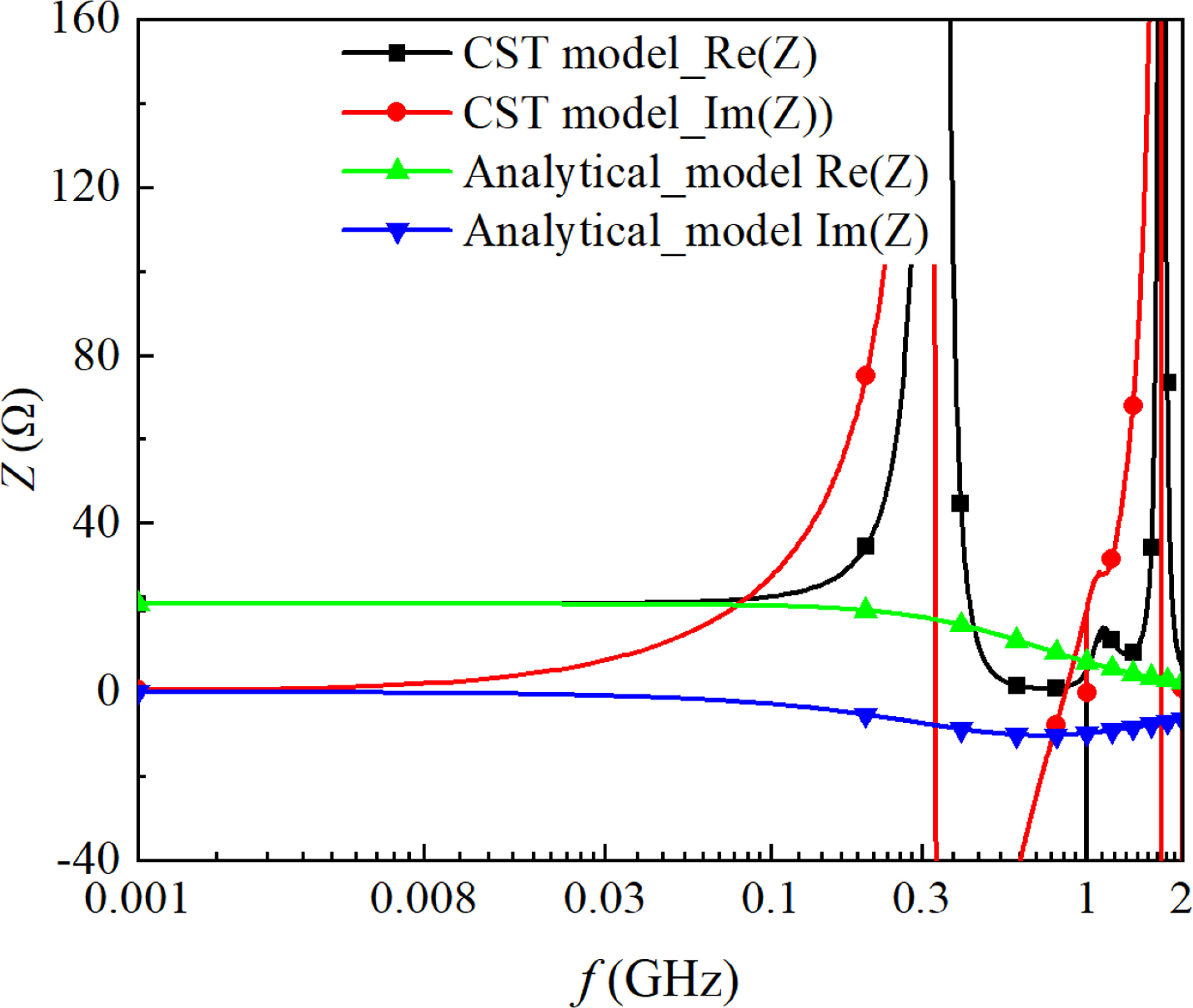
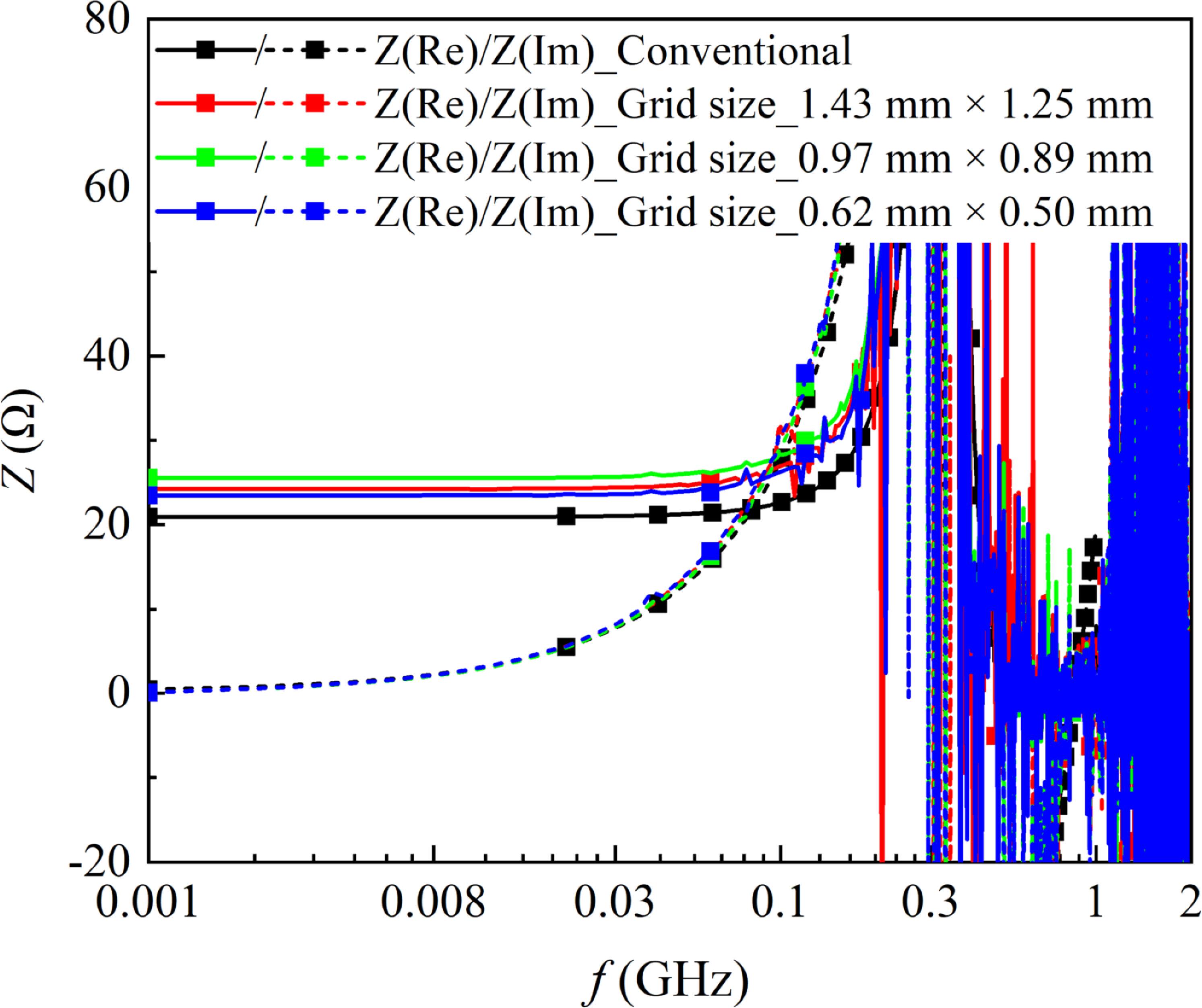
To evaluate the impedance characteristics of the proposed grid-patterned cuvettes, full-wave EM simulations are performed for three configurations, each employing grid electrodes with different grid sizes: 1.43 mm × 1.25 mm, 0.97 mm × 0.89 mm, and 0.62 mm × 0.50 mm, respectively. As shown in figure 3, all configurations display consistent frequency-dependent impedance responses. Below 3 MHz, the saline primarily exhibits resistive behavior. Between 3 MHz and 110 MHz, the impedance response becomes increasingly inductive. A distinct resonance is observed around 200 MHz, indicating a downward shift from the 300 MHz resonance found in the commercial cuvette. This shift is attributed to the geometry of the grid electrodes, which introduces additional reactive components that behave similarly to an RLC resonant circuit. Importantly, the observed resonance remains well above the fundamental operating frequency of 20 MHz. These results highlight the significant role of electrode geometry in shaping the high-frequency impedance response of the system.
Figure 3. Impedance of 40 ul saline versus frequency in different cuvettes. The black, red, green and blue represent the standard, 4 × 9 grid, 9 × 19 grid, and 15 × 25 grid cuvettes, respectively.
Download figure:
Standard image High-resolution imageTable 1 presents a detailed comparison of impedance for different saline volumes within various cuvettes, simulated at 20 MHz. Significantly, impedance is influenced by the grid configuration. Amont them, The greatest impedance is observed in the cuvette with dimensions of 0.97 mm × 0.89 mm, followed by 1.43 mm × 1.22 mm, and then 0.64 mm × 0.50 mm. This variation in impedance can be attributed to the number and size of the grids. In addition, the impedance increment becomes more pronounced as the saline volume increases.
Table 1. Simulated impedance of saline contained in various configuration cuvettes with different volumes at 20 MHz.
Volume (μl)2030405060708090Z_Commercial cuvette (Ω)41.827.820.816.713.911.910.49.3Grid size 1.43 mm × 1.25 mmZ (Ω)48.232.224.820.017.215.013.512.3 Increase (%)15.315.819.219.7623.726.129.832.3Grid size 0.97 mm × 0.89 mmZ (Ω)51.334.426.121.318.115.814.212.8 Increase (%)22.723.725.527.530.232.836.537.6Grid size 0.62 mm × 0.50 mmZ (Ω)46.831.624.219.716.814.813.312.1 Increase (%)12.013.716.318.020.924.427.930.12.4. Electric filed distributionThe electric field distribution across biological samples is the other critical performance metric. To minimize disparities in in vitro experiments, it is essential to ensure a uniform electric field distribution throughout the samples during nsPEF-based electroporation.
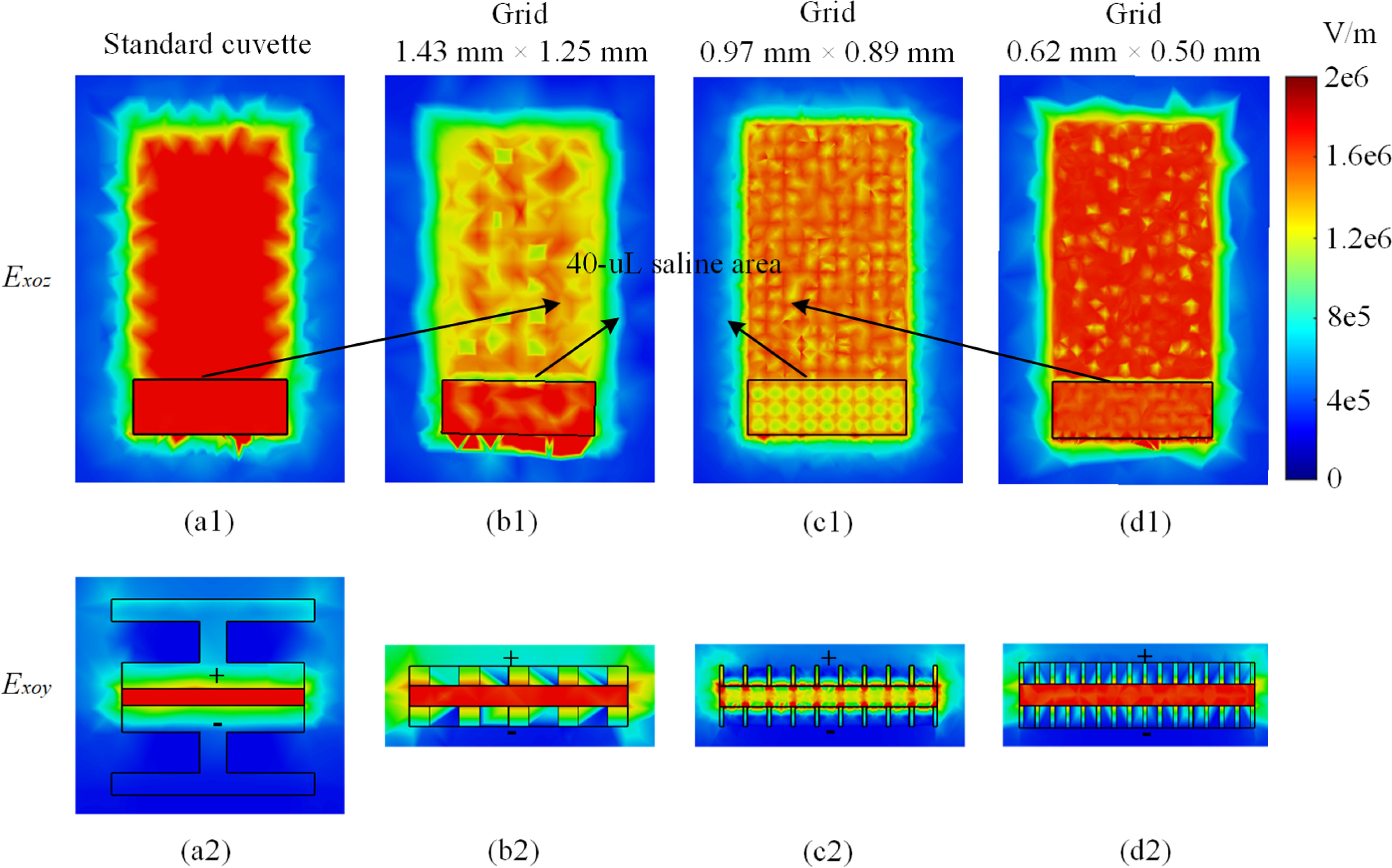
To evaluate the electric field distribution across the three grid configurations, electrostatic simulation is conducted, as shown in figure 4. A commercial cuvette is used as a reference, exhibiting a baseline uniform electric field strength of 20.00 kV cm−1. Among the grid-patterned designs, the configuration with the smallest aperture size (0.64 mm × 0.50 mm) achieves the most uniform field distribution, yielding an average field strength of 19.00 kV cm−1. This is followed by the 1.43 mm × 1.25 mm configuration, which also produces 1.85 kV m−1 but with slightly less uniformity, and the 0.97 mm × 0.89 mm grid, which results in a lower average field strength of 17.40 kV cm−1. These results highlight that grid geometry influences not only impedance but also the uniformity and magnitude of the electric field delivered to the biological sample.
Figure 4. Distribution of the electric field in various grid configuration, where the area within the black frame represents the saline.
Download figure:
Standard image High-resolution image 2.5. Joule depositionSince this experiment involves an in-vitro micro-volume operated at a repetition rate of 1 Hz, the conventional SAR criteria for biological safety is not directly applicable. Instead, it is more appropriate to evaluate the energy deposition and temperature rise per pulse. Given that each pulse lasts only 50 ns once per second, the average thermal power is considered rather than the instantaneous Joule power dissipation, which can be defined as follows,

Based on the given pulse parameters (σ = 1.2 S m−1, τ = 50 ns, and E = 2 kV/1mm), and saline condition (vs = 40 μl), the energy deposition per pulse is approximately 9.6 mJ. The resulting temperature rise per pulse can be estimated by the equation

where  is the mass of the 40 μl saline, and c is the specific heat capacity, approximated by that of water (4180 J (kg.K)−1). The calculated temperature increase of approximately 0.057 °C can be negligible, indicating that the overall heating effect is minimal and primarily acts to limit the instantaneous current. Therefore, the observed biological responses are attributed to non-thermal electroporation mechanisms rather than thermal effects.
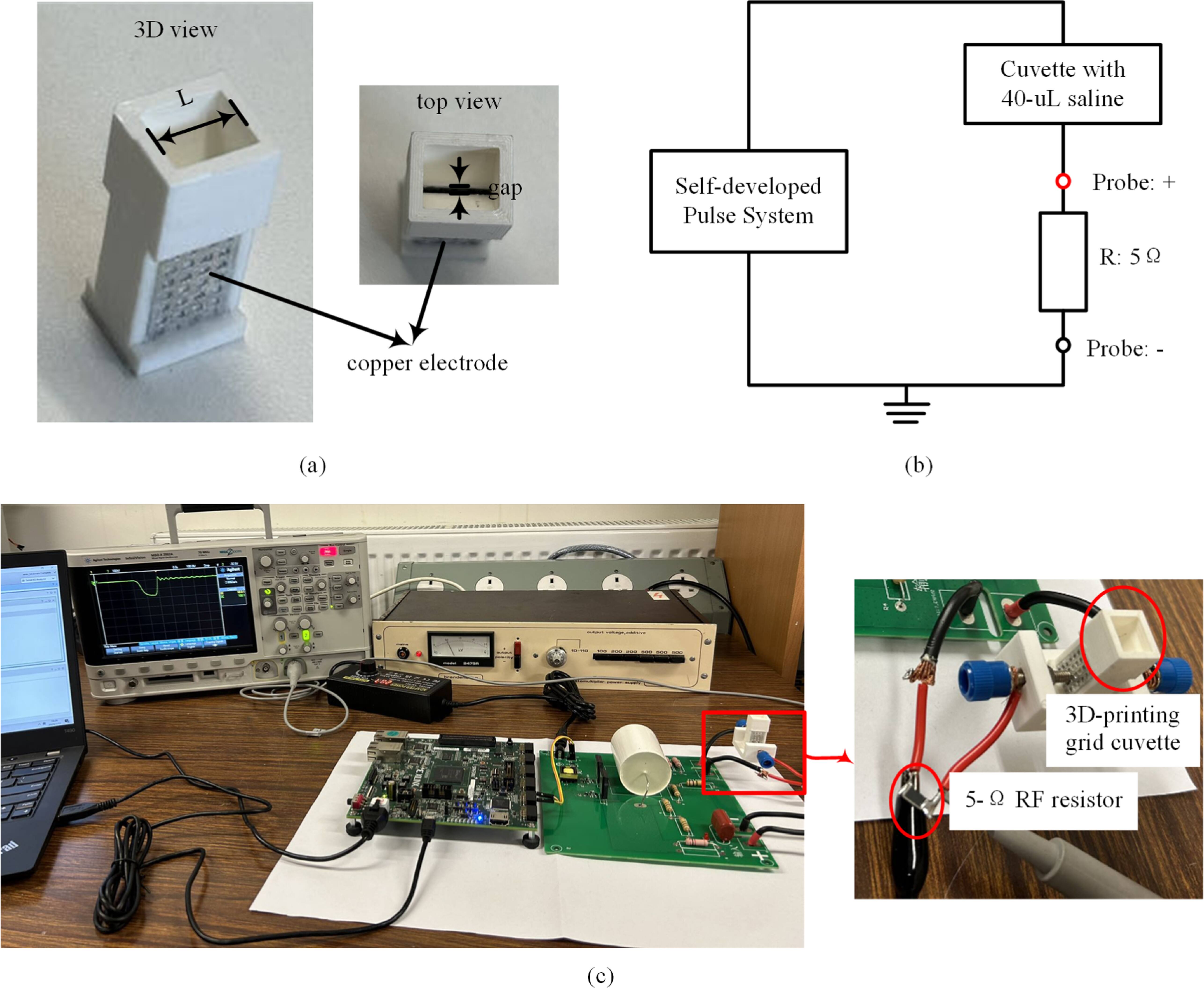
To validate the design concept, a grid-patterned cuvette with a 1-mm gap was fabricated using 3D-printing technology, as shown in figure 5(a). The cuvette body (white area) and the grid electrodes were printed using transparent polylactic acid (PLA) on an Ultimaker S3 printer. To ensure conductivity, aluminum foil was carefully adhered to the surface of each grid electrode. Finally, the main body and the grid electrodes were assembled into a grid cuvette with 1 mm gap. To achieve a balance between electrical performance and fabrication feasibility, the grid aperture was set as 1.22 mm × 1.43 mm, and overall size of each electrode measuring 10.7 mm × 20.97 mm. This configuration offers an effective compromise between bioelectric function and manufacturing complexity. Notably, the contact resistance between the aluminum foil and the grid electrodes can be neglected due to the extremely high electrical conductivity of aluminum.
Figure 5. (a) 3D-printed grid cuvette, (b) diagram of current-voltage method, and (c) measurement setup.
Download figure:
Standard image High-resolution imageTo obtain reliable impedance of the saline in the grid-patterned cuvette under nsPEF-based exposure, a direct I-V method was implemented. The schematic and setup are shown in figures 5(b) and (c). A 5-Ω RF resistor is connected in series to measure the current, which, based on Kirchhoff laws, is identical to the current flowing through the saline. An oscilloscope (Agilent Technologies MSOX2002A) is connected via a high-voltage probe to montior the voltage across the RF resistor. The resulting impedance of 40 μl saline can be obtained under different voltages, as summarized in table 2. The measured average impedance is approximately 25 Ω.
Table 2. Measured impedance of 40-uL saline in the grid cuvette using the I-V method with error ranges.
Input Voltage500100015002000V(meas)_5 Ω (V)84 ± 2.5167 ± 4.2246 ± 6.2329 ± 8.2V(meas)_40 μl (V)420 ± 10.5832 ± 20.81245 ± 31.11646 ± 41.2Z(cal)_40 μl (V)25.0 ± 0.624.9 ± 0.625.3 ± 0.625.0 ± 0.6To emphasize the enhancement of the grid-patterned cuvette, the same measured procedure is applied to a commerical cuvette contain saline of 40 μl, indicating an average impedance of approximately 21 Ω, as presented in table 3. This corresponds to a 19% increase in impedance compared to a commercial cuvette. This enhancement offers several practical advantages for nsPEF-based in vitro applications:
(1)
The increased impedance helps to keep the current below critical safety thresholds, ensuring safe operation under high-voltage pulse conditions.
(2)
The grid-patterned design supports larger sample volumes while maintaining safe current levels, supporting more efficient experimental workflows, particularly in high-throughput or batch processing.
(3)
The ability to handle larger sample volumes per run reduces repeated loading, minimizing redundancy and enhancing reproducibility.
Table 3. Measured impedance of 40-uL saline in the commercial cuvette using the I-V method with error ranges.
Input voltage500100015002000V(meas)_5 Ω (V)98 ± 2.9195 ± 5.9285 ± 8.6369 ± 11.1V(meas)_40 μl (V)410 ± 12.3810 ± 24.31194 ± 35.81539 ± 46.2Z(cal)_40 μl (V)20.9 ± 0.620.8 ± 0.620.9 ± 0.620.8 ± 0.6Overall, these advantages highlight the practicality of the grid-patterned cuvette for in-vitro nsPEF electroporation.
This study presents a grid-patterned cuvette specifically designed to improve the impedance while maintaining a uniform electric field distribution across biological samples. Compared to commerical cuvettes, the grid-patterned cuvette outperforms in bioelectric performance, influenced by both the number and size of the grid elements. Balancing fabrication feasibility and field uniformity, a prototype with grid dimensions of 1.22 mm × 1.43 mm was fabricated using 3D printing. Impedance measurement of saline samples with varying volumes were conducted using the I-V method. For a 40 μl saline sample, the grid-patterned cuvette can achieve 20% improvement in resistance, aligning well with EM. Notably, simulations indicate that impedance enhancement becomes increasingly significant with larger saline volumes. These findings highlight the potential of the grid-patterned cuvette for in vitro nsPEF-based electroporation, particularly in high-conductivity environments.
This research was supported by the CSC-QMUL scholarship under Grant No. 201908610177. The authors are also very thankful to the antenna lab in QMUL for their support and assistance during the fabrication and measurement phases of this work.
All data that support the findings of this study are included within the article (and any supplementary files).
Comments (0)