
Remember me


Pulsed laser ablation in liquids (PLAL) is an increasingly employed nanoparticle synthesis technique, first established in the 1990s . This method involves focusing high-energy laser pulses onto a solid target submerged in a liquid medium . As the laser interacts with the target, it triggers rapid ionisation, heating, and evaporation of the material, leading to plasma formation. The plasma cools down in the surrounding liquid releasing nanoparticles (NPs) into the liquid; the cooling process also generates gas bubbles from the liquid environment. These gas bubbles nucleate, forming a cavitation bubble (CB). Additional NPs are formed within this bubble until it collapses, releasing and ejecting the remaining NPs into the liquid . Although nanomaterials can be produced by alternative physical, chemical, or biological methods , PLAL offers several advantages . Chemical methods are effective at controlling NP size and shape but often require reducing agents and stabilising or capping agents to ensure colloidal stability, which may introduce impurities and raise environmental concerns. Biological routes for synthesising nanomaterials, such as those based on plant extracts, bacteria, or fungi, are indeed eco-friendly and offer advantages like low toxicity and reduced environmental impact; however, they generally offer less control over NP properties. Moreover, other physical methods such as milling, pyrolysis, sputtering, and arc discharge, or gas-phase processes such as flame spray pyrolysis or gas aggregation are highly scalable and productive, though they typically require high temperatures or vacuum systems and may offer limited control over surface chemistry.
Compared with these approaches, PLAL provides high-purity colloids with reduced impurities and byproducts, even allowing for tuning NP size, crystallinity, defects, and optical properties. Conventional batch PLAL setups often exhibit lower productivity than large-scale chemical or gas-phase syntheses; however, recent advances using megahertz-repetition-rate lasers and continuous-flow configurations have significantly increased yield, demonstrating that scale-up is feasible and cost-effective .
Figure 1 provides a comparative overview of these methods, considering the key factors: elemental flexibility, environmental friendliness, synthesis purity, health and safety, productivity, process complexity, and degree of remote controllability. The latter refers to the ability to fully automate and operate the process under closed-loop control. PLAL lends itself naturally to remote monitoring and automation through computer-controlled lasers, scanning systems, and online spectroscopy , although similar automation can also be achieved in chemical synthesis using microfluidics-based reactors .
![[2190-4286-17-22-1]](https://www.beilstein-journals.org/bjnano/content/figures/2190-4286-17-22-1.png?scale=2.0&max-width=1024&background=FFFFFF)
Figure 1: Comparative analysis of the main features of nanomaterial synthesis techniques, that is, chemical, biological, physical, and laser synthesis.
PLAL mechanisms and the ablation dynamics can be described starting with the pulsed emission from the laser source . The laser beam travels through the transparent liquid layer, ideally minimising energy losses due to absorption and avoiding nonlinear optical effects . Upon reaching the target, the laser pulse induces rapid electronic excitation, leading to the injection of electrons into the surrounding liquid, within the first few picoseconds, from 1 to 20 ps . This triggers the formation of a dense plasma composed of the target material components, which remains active for 20 to 200 ps . The plasma expands rapidly, generating a mechanical shockwave in both the target and the liquid, with pressures at the laser’s focal spot reaching tens of gigapascals, but strongly depending on the specific laser conditions . The high pressures induce spallation of the target surface, while the plasma interacts with the liquid, vaporising it partially and forming a cavitation bubble (CB) on a nanosecond timescale . Throughout microseconds, the CB grows and collapses, releasing NPs into the liquid environment . The early stages of laser ablation, along with variations in material density, temperature, and phase states, can be effectively modelled using large-scale atomistic simulations .
PLAL is a simple, fast, and versatile technique that has been employed to produce ligand-free NPs , core–shell structures , heterostructures , nanoalloys , hybrid materials , and complex multielement nanomaterials such as high-entropy alloys . This method enables the synthesis of nanomaterials with exceptional purity from virtually any solid target , including pure metals , semiconductors , or dielectric materials , in organic or inorganic solvents . Although initial NP production rates via PLAL were limited to a few milligram per hour, recent advancements in high-power, high-repetition-rate laser systems , as well as strategies such as the use of diffractive optical elements to create multifocal structures , CB bypassing , reducing the liquid layer , avoiding nonlinear effects , and optimising sample geometry , have significantly increased the production rates up to several grams per hour in specialised setups requiring fast scanning systems and high power (500 W) and repetition rate (10 MHz) picosecond laser sources . Only recently, the employment of diffractive optical elements has enabled the gram-per-hour productivity scale with industrially available picosecond laser sources, still requiring high power sources (100 W) but removing the requirement for high repetition rate and faster scanning speeds .
PLAL-produced nanomaterials have broad applications across different nanotechnology fields, including X-ray radiotherapy , boron neutron capture therapy , viral and microbial growth inhibition , antibacterial agents , anticancer treatments , magnetic resonance imaging contrast agent , photothermal therapy , cell imaging , proton therapy enhancement , fluorescence and colorimetric sensors , surface-enhanced Raman spectroscopy detection , nanofluids for thermal applications , additive manufacturing , or catalysis . The previously mentioned applications of PLAL-derived NPs can be grouped into four major categories, that is, catalysis , advanced materials , sensing and filtration , and bio-applications . Figure 2 schematically illustrates this classification.
![[2190-4286-17-22-2]](https://www.beilstein-journals.org/bjnano/content/figures/2190-4286-17-22-2.jpg?scale=2.0&max-width=1024&background=FFFFFF)
Figure 2: PLAL NP applications, arrows point outwards to the four defined areas, catalysis, advanced materials, sensing and filtration, and bio-applications. Figure 2 was reproduced from (© 2020 E. Fazio et al., published by MDPI, distributed under the terms of the Creative Commons Attribution 4.0 International License, https://creativecommons.org/licenses/by/4.0).
However, several limitations remain that hinder the widespread industrial adoption of PLAL, including the overall yield and scalability, particularly when attempting to synthesise complex nanostructures at industrial volumes, as well as the reproducibility and precise control over NP properties such as shape. As discussed by Jendrzej et al. , when scaling up PLAL, the cost of the laser becomes a negligible factor compared to process efficiency, throughput, and colloid stability. Therefore, optimising ablation conditions (e.g., using high-repetition-rate lasers, flow-through cells, and improved cavitation management) will be critical for enabling commercially viable production .
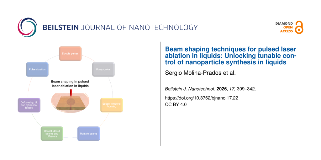
One promising strategy to overcome these limitations involves controlling the spatial and temporal profiles of the laser beam. Spatial beam shaping allows for fine adjustment of energy distribution on the target, influencing ablation efficiency and NP uniformity. Figure 3 provides an overview of representative approaches and the corresponding beam profiles they enable. Similarly, temporal pulse shaping modifies the interaction time and heat generation and dissipation, allowing for better control of overheat accumulation and nonlinear effects during ablation. These approaches provide a path toward more consistent and tunable NP synthesis, further unlocking the potential of PLAL.
![[2190-4286-17-22-3]](https://www.beilstein-journals.org/bjnano/content/figures/2190-4286-17-22-3.png?scale=2.0&max-width=1024&background=FFFFFF)
Figure 3: Schematic illustration of spatial beam shaping strategies in PLAL. Different beam profiles can be generated from the standard Gaussian mode: top-hat, doughnut-shaped, and multiple-beam configurations. Such modifications influence the local fluence distribution on the target, thereby affecting ablation efficiency, NP size distribution, and colloid uniformity.
Spatial and temporal beam shaping in material processingThe spatial focusing of the laser beam on the sample directly influences the ablation efficiency and the quality of the produced NPs. The most widely used PLAL system in different laboratories around the world consists on a convergent lens with the laser beam perpendicular to the target . However, the laser ablation process is highly sensitive to both the spatial and temporal profiles of the beam. While there are already some studies exploring the effects of beam shaping, this field remains largely underexplored. Further advancements in spatiotemporal beam shaping techniques hold significant potential to greatly enhance control over NP synthesis by PLAL.
In the context of PLAL, the NP yield is typically defined as the mass of NPs collected per unit of time (milligram per hour) or per unit of laser energy (milligram per joule). The ablation rate corresponds to the total mass removed from the target per unit of time or per pulse (milligram per hour, milligram per pulse), while the collection efficiency denotes the fraction of this ablated mass ultimately recovered as colloidal NPs. Quantification can be carried out by gravimetric analysis of the colloid, either collecting the entire suspension, evaporating the solvent to dry it, and weighing the residue, or by measuring target mass loss before and after ablation, which allows for an estimation of collection efficiency. Greater precision is obtained by inductively coupled plasma-based (ICP) techniques (ICP mass spectrometry or ICP optical emission spectroscopy) and atomic absorption spectroscopy, particularly for metallic targets, as they determine the concentration in a representative colloidal aliquot. Complementary methods include UV–vis spectroscopy with calibration standards or thermogravimetric analysis in the presence of organic species or adsorbates .
When reporting NP yields, several practical issues must be considered. Collection efficiencies are generally below unity, meaning that the ablated mass does not directly equal the NP mass in suspension. Incomplete solvent evaporation or residual organics can bias gravimetric results, making vacuum drying preferable. NP adhesion to container walls requires vessel washing, and aggregation during or after ablation may need sonication or size-separation steps. Overall, gravimetry provides accessible but sometimes overestimated values, whereas ICP-based approaches offer more accurate and reproducible quantification, facilitating reliable comparison of different PLAL conditions.
From a spatial perspective, the beam profile can be modified from the standard Gaussian profile into top-hat, doughnut-shaped, or multiple beams using optical elements, including cutting-edge technology such as metamaterials or refractive, reflective, or diffractive elements . Beam shaping can be accomplished through a variety of advanced optical technologies, applied either individually or in combination, as shown in Figure 3. As a general strategy for imaging and material processing, beam shaping technologies represent a research field covered in numerous reviews . In the subsequent sections, this review offers a more detailed discussion of beam-shaping methodologies for nanoparticle synthesis and the underlying optical mechanisms including its influence on ablation efficiency, size control, and colloidal stability.
Refractive elements rely on the interaction of light with a transparent material with a different refractive index than air. Standard refractive optics elements such as lenses often suffer from aberrations and can introduce temporal pulse broadening due to the wavelength dependence of the refractive index. Alternative refractive optics technologies include dynamic lenses and freeform optics (both in refraction and reflection) . Unlike traditional lenses, freeform optics can generate complex and exotic light structures that go beyond simple focusing, allowing for custom-shaped intensity distributions at the target. This technology permits the creation of arbitrary beam shapes, enabling more intricate control of the laser interaction with the material, which is especially useful for advanced applications requiring customised energy deposition patterns. Diffractive elements offer the advantage of being thin and lightweight and allow for the generation of user-defined beam patterns through controlled light diffraction produced by micro- or nanostructured glasses or surfaces. However, they are specifically designed for a single wavelength, and their use with ultrashort pulses can lead to substantial temporal pulse broadening .
Laser beam shaping technologies can be also categorised into static and dynamic systems. Static systems include components such as microlens arrays, cylindrical lenses, diffractive lenses, and flat optics, which provide fixed spatial beam profiles . For dynamic beam control, spatial light modulators (SLMs) are employed, with liquid crystal modulators, membrane mirrors, and digital micromirror devices (DMDs) being the most employed technologies . Liquid crystal modulators are well suited for modulating both amplitude and phase , but they operate at relatively slow speeds, typically in the range of a few hertz. In contrast, DMDs offer very high modulation speed, though they encode information in a binary format, limiting their flexibility for some applications. Membrane mirrors, in contrast, allow for complete control of the beam including intensity and full surface actuation. Nevertheless, their low number of actuators restrict the precision of the modulation, making them primarily useful for correcting optical aberrations. Although SLMs have demonstrated their relevance in material processing, their application in PLAL remains largely underdeveloped and presents significant opportunities for further exploration.
From the temporal pulse perspective, the main strategies for material processing are the generation of double pulses or pulse bursts , as well as modifying the temporal profile of the pulsed beam. In the first case, the technological developments of lasers in the last decade have allowed for the generation of megahertz and gigahertz bursts using acousto-optic devices within the laser cavity. In the second case, pulse compressors enable the creation of user-defined temporal pulse profiles using Fourier space shaping or direct space-to-time pulse shapers . Temporal pulse shaping has been employed in laser material processing to reduce the required laser fluence for processing and to maximise ablation efficiency through minimisation of thermal dissipation . However, pulse shaping in PLAL still represents a barely explored approach, being mostly limited to experiments with controlled temporal delays between pulses. Further evaluating the possibilities of pulse shaping in PLAL holds the potential to provide enhanced control over laser–matter interactions, facilitating more precise NP synthesis.
Advanced spatial beam shaping in PLAL The role of spatial beam shaping in PLALThe spatial profile of the laser beam plays a pivotal role in influencing all stages of the PLAL process. It governs critical features of PLAL, from the laser interaction with the liquid and the target to the subsequent modifications in the shape and dynamics of the CB, and rate, depth and area of ablation. These interdependent processes ultimately define the properties of the NPs, such as their size and distribution. The influence of these factors and their interrelations will be discussed in this section emphasising the role of the irradiance, also called intensity, (watt per square centimetre) and the fluence (joule per square centimetre) of the laser beam. Both variables strongly depend on beam size and shape and fundamentally describe the effect of beam shaping, in contrast to a parameter like pulse energy, which remains constant if the spatial beam profile is modified.
When the laser enters the liquid, it can be absorbed, that is, water and most of the organic solvents absorb radiation for wavelengths in the near infrared; this produces heat that can cause vaporisation of the liquid layer once the fluence threshold of vaporisation is reached . At high irradiances, in the gigawatt per square centimetre range, nonlinear optical effects such as self-focusing, supercontinuum generation, multiphoton ionisation, filamentation, and optical breakdown can become significant . These effects can influence how the beam propagates through the liquid and interacts with the target and have a strong dependence on the beam profile . Self-focusing is a nonlinear optical process induced by a local modification of the refractive index of a material due to the propagation of an intense laser beam due to the Kerr effect . Self-focusing is a power-dependent effect and occurs in water at a threshold laser power of the order of 1 MW that corresponds, for a typical irradiation spot size of 100 μm, to an irradiance threshold of ≈1010 W·cm−2. When the irradiance exceeds the self-focusing threshold at 1010 W·cm−2, several nonlinear processes such as self-phase modulation, four-wave mixing, Raman scattering, and self-steepening cause severe spectral broadening, generating a supercontinuum. In addition to self-focusing in the solvent, it is important to consider the influence of NPs already present in the liquid on the optical breakdown threshold. Dispersed NPs act as additional scattering and absorption centres, leading to local field enhancement in their vicinity. These effects facilitate multiphoton absorption and avalanche ionisation processes, effectively lowering the breakdown threshold of the liquid compared to NP-free conditions. This is shown by the fluence dependence of the generation rate of hydroxyl radicals during optical breakdown in water in the presence of terbium NPs. When the fluence increases from 60 to 140 J·cm−2, the radical yield with oxidised NPs rises by over an order of magnitude . Moreover, according to Davletshin et al., plasmonic coupling in aqueous Au nanospheres leads to enhanced local fields. This leads to a reduction via near-field amplification of up to four orders of magnitudes in the effective optical breakdown threshold under 3 ps irradiation, compared to the base liquid without NPs (8.5 × 10¹¹ W·cm−2) . Several strategies, both statical and dynamical , have been considered to modify the spatial beam profile of the laser with an impact on the supercontinuum effect. Considering that the supercontinuum can modify the size of the NPs in a colloid due to fragmentation , it can be a tool to control NP distribution during or after PLAL.
For irradiances that exceed 1012 W·cm−2, laser filamentation can occur. This is a complex process that results from the dynamic balance between self-focusing and plasma-defocusing. An example of filamentation produced in a PLAL setup can be observed in Figure 4 . Initially, high-intensity laser irradiation inside the liquid medium triggers multiphoton ionisation and tunnel ionisation, generating free electrons due to the high peak power. The excess of electrons and ions induced by the multiphoton ionisation has been used in reactive ablation for the fabrication of NPs and hybrid colloidal NPs . In other applications, dynamic control of the filaments can be achieved by employing spatial light modulation .
![[2190-4286-17-22-4]](https://www.beilstein-journals.org/bjnano/content/figures/2190-4286-17-22-4.jpg?scale=2.0&max-width=1024&background=FFFFFF)
Figure 4: (a) Experimental setup for the record of filamentation produced in a liquid. (b) Laser focusing in water, glycerol, and ethanol; the laser is on the left-hand side. Pulse energies: 100, 240, 450, and 785 µJ; pulse duration: 150 fs; central wavelength: 775 nm. Figure 4a and Figure 4b were reproduced from (© 2022 D. Chaitanya Kumar Rao et al., published by Springer Nature, distributed under the terms of the Creative Commons Attribution 4.0 International License, https://creativecommons.org/licenses/by/4.0).
Finally, the optical breakdown irradiance threshold in aqueous media is about 1 × 10¹⁰ W·cm−2. This process is physically observed by bubble formation in the liquid . The dissociation of the liquid due to multiphoton ionisation leads to the formation of a hot plasma with temperatures reaching 104 K. Subsequently, plasma recombination begins, and the high-temperature plasma is replaced by vaporised fluid, leading to the creation of microbubbles and mechanical effects such as shock wave emission and cavitation. In general, these microbubbles cause laser energy losses and distortion of the laser spatial profile due to scattering and should be avoided to maximise PLAL productivity and control the irradiation parameters on the target.
The fluence (Φ0), that is, the energy per unit area, is another key parameter of the laser that can be modified by spatial shaping. The fluence directly influences most of the properties of the ablation process as the size of the CB, where the maximum bubble volume scales linearly with the laser fluence for the high-fluence range, 100–200 J·cm−2. The NP size distribution is also affected by the fluence, obtaining smaller NPs for low fluences of 0.5–4.0 J·cm−2. The NP composition is also affected by the fluence. An increase of the laser energy leads to a higher concentration of gas, for example oxygen atoms, that increase O content in the produced NPs and affect the morphology . Regarding the ablation efficiency, a maximum is reported for ablation in air for Φ0 = e2Φth, where Φth is the ablation threshold . In liquids, ablation efficiency is usually determined experimentally due to energy losses and beam modification through confinement, plasma–liquid interactions, and cavitation bubbles. Dittrich et al. found that the ablation threshold for Au in air is ca. 1.9 times higher than in water , and Sun et al. reported a reduction from 2.22 J·cm−2 (air) to 1.02 J·cm−2 (liquid-assisted) . Therefore, the air-related formula is often used, but complemented by an empirical correction factor to account for liquid effects as proved by Intartaglia et al. for Si NP production with a picosecond laser and Kanitz et al. for Fe NP production with femtosecond laser . Up to now, control of the fluence has been performed by varying the laser pulse energy . In the last years, other approaches to modify the fluence through changing the spatial profile have emerged .
Focal spot shape conformation in PLALThe interaction of the laser with the target and the generated colloid depends not only on the beam fluence but also on the shape. The focusing systems employed in the synthesis of the NPs affect their properties. Therefore, this section will review the main beam-shaping techniques that are used in PLAL for influencing NP formation. We will divide the section into two different subsections. In the first one, we will consider spatial beam profile variations in conventional PLAL systems (defocusing, tilting, and the incorporation of cylindrical lenses). In the second subsection, we will focus on systems where an external element is added to modify the beam profile into a non-Gaussian beam (Bessel beam, doughnut beam, and speckle pattern).
Conventional spatial beam control. Although the determination of the focused laser beams in air can be done directly from the ablated spots at different lens–target distances, in liquids and with ultrashort laser pulses this procedure is not so evident. The diameter of the ablated spots under different water layers for a 120 fs pulsed beam with a spherical lens of 40 mm focal length is shown in Figure 5. When ablation is carried out in air, the craters caused in the target have the smallest diameter when the relative geometric focal length of the lens coincides with the target, dzL = 0. The diameter of the craters increases when the relative position of the lens–objective system moves towards the target (dzL < 0) or away from it (dzL > 0). Consequently, the smaller the ablated spot, the higher the fluence, and a higher productivity can be achieved . In comparison, when ablation takes place within a liquid, the ablated spot diminishes until vanishing with the increment of the lens position dzL. However, when NPs are generated in liquid using femtosecond pulses, the largest ablated mass does not occur for the lens–target position corresponding to the smallest ablated spot. In fact, the maximum NP productivity with a 10 mm liquid layer was achieved for dzL = +2 mm. According to Figure 5, the smallest spot found for these parameters was at dzL = +4 mm. This 2 mm difference in the lens position induces a 260 times higher Au colloid concentration. For this reason, defocusing is a simple, alternative technique to increase NP production by modifying the energy distribution when ablating the target. Defocusing plays a dual role depending on whether the local fluence is maintained. When the beam is defocused without power compensation, the fluence at the target decreases, leading to lower plasma temperatures and reduced ablation efficiency, which generally results in smaller NPs with narrower size distributions.
![[2190-4286-17-22-5]](https://www.beilstein-journals.org/bjnano/content/figures/2190-4286-17-22-5.png?scale=2.0&max-width=1024&background=FFFFFF)
Figure 5: Top: Ablated spot diameter on a silicon wafer comparison between air and with 10 mm water layer. Bottom: Effect of lens position using a spherical lens with 40 mm of focal length in different liquid layers. Figure 5 was reproduced with permission from . Copyright 2011 American Chemical Society. This content is not subject to CC BY 4.0.
When the laser power is increased to compensate for the defocusing, the fluence is kept constant, but a larger ablation area is irradiated, which increases NP production. The higher colloidal concentration enhances aggregation, often resulting in larger mean particle sizes . Furthermore, the precision of the focusing can play a crucial role in the physicochemical properties of the colloids. Ryabchikov et al. have demonstrated that the optical properties of Si/Au NPs, their structure, as well as their chemical composition can be modified by defocusing . Defocusing 0.5 mm inside the target led to enhanced chemical stability of the colloids and increased concentration. Moreover, NP size control could be achieved by defocusing. The hydrodynamic diameter increases with defocusing, with the smallest diameter achieved when the focal spot is placed on the target surface (Figure 6). Therefore, the reported increase or decrease in NP size under defocusing is not contradictory but rather reflects the different strategies used to control fluence during the process.
![[2190-4286-17-22-6]](https://www.beilstein-journals.org/bjnano/content/figures/2190-4286-17-22-6.png?scale=2.0&max-width=1024&background=FFFFFF)
Figure 6: (a, b) Nanoparticle concentrations, (c, d) hydrodynamic diameters, and (e, f) ξ-potential of one and two-component NPs prepared by PLAL, at different focus positions. Figure 6a–f was reproduced from (© 2025 Y. V. Ryabchikov et al., published by MDPI, distributed under the terms of the Creative Commons Attribution 4.0 International License, https://creativecommons.org/licenses/by/4.0).
Another way to modify the beam shape without changing the PLAL system is by tilting either the sample or the incident beam. The effect of target tilt along the laser irradiation direction has been investigated by Al-Mamun et al. while producing spherical Al2O3 NPs by nanosecond laser ablation in water . Tilting the target results in smaller particles with a narrower distribution due to the larger spot and lower fluence . Morphology and shape of the ablated NPs remain constant. The produced NPs were spherical with an average particle size ranging from 8 to 18 nm for different laser parameters.
Conventionally, spherical lenses are used in PLAL. Unlike ablation with spherical lenses, ablation with cylindrical lenses modifies the spot size into an elliptical shape, increasing the area. Marrapu et al. demonstrated that the use of cylindrical lenses in PLAL can lead to the formation of nanoribbons , and this may be attributed to two main mechanisms. First, the initially formed Ag nanospheres could undergo nanowelding under the influence of a line-shaped light sheet produced by cylindrical focusing, leading to chain- or ribbon-like structures. Second, the cavitation bubble generated during ablation and its subsequent oscillations play a critical role. Under cylindrical focusing, the cavitation bubble adopts an elongated shape that differs from the typical spherical morphology observed with circular beams . This anisotropic geometry alters the internal pressure distribution and collapse dynamics, affecting the interaction between the plasma plume, shock waves, and the surrounding liquid. Consequently, both the light-induced welding and the anisotropic cavitation bubble dynamics are key factors determining the formation of the elongated nanostructures observed under cylindrical focusing.
The PLAL experiments with cylindrical lens were performed with a 2 ps laser and a cylindrical lens of 45 mm focal length, using pulse energies between sensing and filtration of 1.0 and 1.4 mJ at 800 nm wavelength . It was observed that at 1.2 mJ pulse energy, the fabrication of Ag nanoribbons longer than 0.6 µm were synthesised (Figure 7).
![[2190-4286-17-22-7]](https://www.beilstein-journals.org/bjnano/content/figures/2190-4286-17-22-7.jpg?scale=2.0&max-width=1024&background=FFFFFF)
Figure 7: TEM images of Ag nanoribbons produced by cylindrical lens ablation at a pulse energy of 1.2 mJ. Ag nanowires/ribbons with an average length of 0.5–1.0 μm. The inset shows the SAED patterns, which reveal the crystalline phase of Ag nanowires. Figure 7 was reproduced from (“Silver nanoribbons achieved by picosecond ablation using cylindrical focusing and SERS-based trace detection of TNT“, © 2020 H. Marrapu et al., published by The Royal Society of Chemistry, distributed under the terms of the Creative Commons Attribution-NonCommercial 3.0 Unported Deed License, https://creativecommons.org/licenses/by-nc/3.0/). This content is not subject to CC BY 4.0.
External elements for spatial beam shaping. The spatial profile of a beam plays a crucial role in laser–matter interaction, influencing the efficiency, precision, and morphology of the ablated material. Therefore, introducing external optical elements that modify the laser beam profile represents an interesting approach to provide further control to the PLAL process.
One of the beam profiles generated by external optical elements are Bessel beams. Bessel beams are widely used in various optical and engineering applications due to their ability to propagate long distances almost without diffraction. Compared to Gaussian pulses, the Bessel beams have a much longer focus and can be considered optical needles. Quasi-Bessel zeroth-order beams can be created by axicon optics (conical lenses), which generate interference of an incoming Gaussian laser beam along the optical axis, thus forming a long focal line. The radial distribution of intensity in a zeroth-order Bessel beam represents a central bright spot surrounded by rings of much smaller intensities so that their spacing can be approximated by the Bessel function J0. The anatomy of the quasi-Bessel beam propagation in space is shown in Figure 8 with a detailed view of its spatiotemporal shape including the evolution of the cross-sectional structure . Two laser beams, one continuous wave (CW) and a femtosecond pulsed laser, have been compared showing very similar structures, underlying the long effective working distances of the intense laser needle.
![[2190-4286-17-22-8]](https://www.beilstein-journals.org/bjnano/content/figures/2190-4286-17-22-8.jpg?scale=2.0&max-width=1024&background=FFFFFF)
Figure 8: (a, b) Transverse distributions of Bessel-like beams observed at various distances (Z) from the axicon for (a) CW HeNe and (b) femtosecond (795 nm wavelength, 35 fs pulse duration) lasers. (c, d) Longitudinal profiles of CW and femtosecond laser beams, respectively. Intensities are normalised to the peak values in the two cases. Figure 8a–d was reproduced with permission from , © 2017 Optical Society of America. This content is not subject to CC BY 4.0.
For PLAL, Bessel beams are still not widely used. This can be related to the very small effective diameter of the beam on the material surface. However, an axicon-generated laser beam has been shown to allow for better control of NP size and to offer an advantage in terms of alignment and reproducibility due to the long length of the central lobe of the Bessel beam . A narrow size distribution of Ag NPs obtained by femtosecond Bessel beam irradiation of a silver target in acetone is shown in Figure 9. As an example, the Bessel-beam-processed surface results in a giant enhancement of the SERS signal of the explosive molecule CL-20 . Thus, NP synthesis in liquids using Bessel beams can provide an additional opportunity for control over colloidal properties.
![[2190-4286-17-22-9]](https://www.beilstein-journals.org/bjnano/content/figures/2190-4286-17-22-9.jpg?scale=2.0&max-width=1024&background=FFFFFF)
Figure 9: Left: TEM image of a Ag colloid prepared by laser ablation in acetone by femtosecond Bessel beams at a pulse energy of 1000 μJ. Right: Field-emission scanning electron microscopy image of a Ag target processed with Bessel beam at energy 1000 μJ. The inset shows the SERS spectrum of the explosive molecule CL-20 at 5 µM concentration (red curve) from the laser-exposed Ag surface. For comparison, the blue curve represents the 0.1 M CL-20 Raman spectra obtained from a silicon wafer. Figure 9 was used with permission from (“Fabrication of nanoparticles and nanostructures using ultrafast laser ablation of silver with Bessel beams”, by G. K. Podagatlapalli et al., Laser Phys. Lett., vol. 12, article no. 036003, published on 13 February 2015; https://doi.org/10.1088/1612-2011/12/3/036003); © 2015 IOP Publishing; permission conveyed through Copyright Clearance Center, Inc. All rights reserved. This content is not subject to CC BY 4.0.
Doughnut-shaped (DS) ring-like beams (also called dark-hollow beams) represent a wide class of spatially shaped light beams with controlled ring intensity and zero central intensity, that is, with phase singularity at the beam centre. Depending on the polarisation, the DS beams can be classified into two classes, those that carry optical angular momentum (OAM) and those that do not. The latter ones are usually radially or azimuthally polarised and, because of the cylindrical symmetry polarisation, they are also called cylindrical vector beams. The beams carrying OAM typically have circular polarisation and represent a subclass of vortex beams. Radially polarised DS beams can be focused on a spot size significantly smaller than conventional Gaussian beams and avoid overheating of the central irradiated regions . DS beams appear particularly attractive for PLAL with ultrashort laser pulses due to the high damage threshold and the possibility of simply switching from radial to azimuthal polarisation. To generate vortex beams with their helical/twisted wavefronts, spiral phase plates are typically used to produce beams with pre-defined OAM modes.
One of the schemes to create vortex beams is shown in Figure 10a . The material ablated with such a beam has been shown to form twisted nanostructures on metal surfaces with controlled chirality . They are formed due to the involvement of ablated/molten material in a spiral motion of the vector vortex beam as illustrated in Figure 10c.
![[2190-4286-17-22-10]](https://www.beilstein-journals.org/bjnano/content/figures/2190-4286-17-22-10.jpg?scale=2.0&max-width=1024&background=FFFFFF)
Figure 10: (a) A scheme of the experimental setup for nanostructuring with the nanosecond vortex beams. (b) Vortex-beam intensity distributions measured in the focal plane of the microscope objectives with different NAs. (c) A sketch of vortex-beam-induced formation of twisted Ag nanojets. A SEM image of a twisted nanojet is shown on the right with the red arrows indicating the rotation direction. (d, e) Top views of SEM images of twisted Ag nanojets produced under single-pulse ablation of 500 nm thick Ag film by nanosecond vortex pulses with opposite signs of helicity. Figure 10a–e was reproduced with permission from , © 2017 Optical Society of America. This content is not subject to CC BY 4.0.
The spatial distribution of the laser fluence Φ(r) of a DS beam along the radial coordinate r is well described by the following equation :
![[2190-4286-17-22-i1]](https://www.beilstein-journals.org/bjnano/content/inline/2190-4286-17-22-i1.svg?max-width=590&scale=1.18182) (1)
(1)where E0 is the pulse energy, and w0 is the waist of the corresponding Gaussian beam hosting the doughnut. According to Equation 1, the beam fluence is zero at the centre (r = 0) and has a maximum at a distance ![[Graphic 8]](https://www.beilstein-journals.org/bjnano/content/inline/2190-4286-17-22-i11.svg?max-width=637&scale=1.18182) from the centre.
from the centre.
The pulse energy of a DS beam should be ≈2.7 times higher than the corresponding Gaussian beam to induce ablation if we assume that the ablation threshold is unaltered by the ring intensity distribution. Figure 11 shows simulated intensity distributions of a Gaussian and DS beam with the same pulse energy .
![[2190-4286-17-22-11]](https://www.beilstein-journals.org/bjnano/content/figures/2190-4286-17-22-11.jpg?scale=2.0&max-width=1024&background=FFFFFF)
Figure 11: Simulated intensity distributions. (a) Gaussian beam; (b) DS beam with the same pulse energy; (c) cross-sectional intensity profiles of the Gaussian and DS beams. The lines show the 1/e2 intensity levels for both beams. Figure 11a–c was reproduced from (© 2021 Y. Tang et al., published by MDPI, distributed under the terms of the Creative Commons Attribution 4.0 International License, https://creativecommons.org/licenses/by/4.0).
When a DS pulse is focused inside a liquid at a fluence above the liquid breakdown, a ring CB is generated, followed by a series of transient phenomena . The evolution of the DS-laser-produced bubble is much more complicated than that of a typically semispherical bubble induced by a Gaussian beam. Figure 12 illustrates the early-stage dynamics of bubbles generated in water by two DS beams with 6 ns, 532 nm pulses (Figure 12a) and 150 ps, 800 nm pulses (Figure 12b). Under both irradiation conditions, the DS beam generates an annular CB and two shock waves, an outer wave moving outward and an inner wave converging toward the centre. After ≈50 ns, the inner wave reaches the focus, reverses direction, and triggers a secondary bubble. As this diverging wave interacts with the annular bubble, it induces a tertiary bubble cloud that vanishes within approx. 100 ns. Finally, the central bubble collapses after 1–2 µs, and the annular bubble fragments into cylindrical bubbles within approx. 100 µs. This evolution differs from Gaussian pulses in liquids, where a single bubble exhibits large-amplitude oscillations and only external shock waves are emitted .
![[2190-4286-17-22-12]](https://www.beilstein-journals.org/bjnano/content/figures/2190-4286-17-22-12.jpg?scale=2.0&max-width=1024&background=FFFFFF)
Figure 12: Time-resolved images of CBs in water produced by DS laser pulses at early evolution stages. (a) Laser wavelength 532 nm, pulse duration 6 ns, F0 = 25 J·cm−2, rD = 68 µm. (b) Wavelength 800 nm, pulse duration 150 ps, E0 = 0.5 mJ, rD = 95 µm. Figure 12a and Figure 12b were reprinted with permission from , Copyright 2011 by the American Physical Society. This content is not subject to CC BY 4.0.
The evolution of CBs induced by DS beams in liquids can influence NP formation in PLAL by acting as nanoscale reactors. Modifying CB dynamics directly affects nucleation, offering new ways to tailor NP properties . Despite the advantages of DS beams in various laser applications, their use in PLAL for NP synthesis has only recently been explored by modifying the distribution size of metal NPs . Studies comparing picosecond Gaussian and DS beams on different targets (metal, metal oxide, and alloy) showed that DS pulses significantly reduced NP size, narrowed size distribution, and improved sphericity. The NPs’ size distribution shows only weak dependence on pulse energy. No significant variation of the Au NP size distribution was observed using 85 and 217 µJ pulses . Instead, the observed effects are linked to the modified geometry and dynamics of the cavitation bubble under DS irradiation. The ring-shaped energy deposition alters plasma confinement and leads to cavitation bubbles with asymmetric expansion and collapse, reducing the bubble lifetime. These modified bubble dynamics influence nucleation and quenching rates, thereby limiting coalescence and favouring the formation of smaller NPs. Figure 13 compares SEM images and size distributions of Au NPs produced by PLAL in water with both laser beams. SEM analysis of Au NPs revealed that DS pulses suppressed aggregation, eliminating large particles, unlike Gaussian beams, which produced size distributions with high-size tails. Additionally, DS-induced CBs had shorter lifetimes than those generated by Gaussian pulses, with the same pulse energy, possibly reducing NP aggregation. Therefore, DS laser pulses offer a promising approach for precise control over NP size and shape uniformity, although further studies are needed to elucidate the mechanisms involved.
![[2190-4286-17-22-13]](https://www.beilstein-journals.org/bjnano/content/figures/2190-4286-17-22-13.jpg?scale=2.0&max-width=1024&background=FFFFFF)
Figure 13: Comparison of gold NPs produced by PLAL with picosecond radially-polarised DS and linearly polarised Gaussian laser beams at the same pulse energy of 85 µJ. (a, b) SEM micrographs of NPs obtained using the DS and Gaussian beams, respectively. (c) NP size distributions showing the number of NPs analysed N, the median diameter ⟨D⟩, and polydispersity index w values derived from the log-normal approximations (solid lines). Figure 13a–c was reproduced from (© 2025 A. R. Altakroury et al., published by Beilstein-Institut, distributed under the terms of the Creative Commons Attribution 4.0 International License, https://creativecommons.org/licenses/by/4.0).
In addition to PLAL, related approaches such as laser fragmentation in liquids (LFL) can also be employed, in which preformed colloidal NPs are irradiated to induce size reduction or reshaping. Zheng et al. showed that the use of diffractive elements/diffusers can contribute to a more efficient control of the NP size, thanks to better energy redistribution . Commonly, a laser beam with flat-top shape is considered to maximise laser–matter interaction. Instead, a diffused laser beam could be crucial if the process of interest has a fluence or intensity threshold. The efficiency of size-reduction of colloidal NPs was improved by a counterintuitive redistribution of laser energy, that is, the formation of speckle patterns by incorporating a diffuser (Figure 14).
![[2190-4286-17-22-14]](https://www.beilstein-journals.org/bjnano/content/figures/2190-4286-17-22-14.jpg?scale=2.0&max-width=1024&background=FFFFFF)
Figure 14: (a) Experimental setup. Diffuser 1: holographic. Diffuser 2: glass diffuser or Scotch tape. Pulse energies of 6, 15, and 25 mJ after aperture 1 correspond to laser fluences of 13, 34, and 56 mJ·cm−2 at the cuvette. (b) Optical images, spatial beam profiles, and X–Y cuts of the spatial beam profiles at cuvette position through holographic and glass diffuser, and Scotch tape. Figure 14a and Figure 14b were used with permission from (“Enhancing laser-nanoparticle interactions by diffused laser beams: efficient size-reduction of nanoparticles”, by X. Zheng et al., J. Phys. D. Appl. Phys., vol 55, article no. 275106 published on 20 April 2022; https://doi.org/10.1088/1361-6463/ac6400); © 2022 IOP Publishing; permission conveyed through Copyright Clearance Center, Inc. All rights reserved. This content is not subject to CC BY 4.0.
Systematic results for Ag and Au NPs have been reported. The physical origin of the efficiency of the diffused laser beam is the redistribution of laser energy so that the local laser fluence exceeds the size-reduction threshold. Figure 15 compares the UV–vis spectra of colloidal Ag NPs irradiated with normal and diffused beams at pulse energies of 15 and 25 mJ (fluences of 34 and 56 mJ·cm−2). As seen in Figure 15a, at 15 mJ, the standard beam has minimal impact on NP size, with the surface plasmon resonance (SPR) peak at 390 nm remaining weak even after 60 min of irradiation. In contrast, the diffused beam at the same energy reduces NP size rapidly, and the 490 nm peak disappears within 10 min (Figure 15b). A slight blue shift of the SPR peak between 10 and 60 min suggests further size reduction over time. At 25 mJ, the standard beam also induces size reduction (Figure 15c), but less effectively than the diffused beam at 15 mJ. The diffused beam at 25 mJ (Figure 15d) achieves even greater efficiency, further reducing NP size. Additionally, the SPR peak width narrows, indicating a more uniform size distribution. Overall, the diffused beam enhances both NP size reduction and distribution uniformity more effectively than the standard beam, showing the possibilities that spatial beam shaping can offer in NP control.
Comments (0)